Figure 2-10. Basic Mechanical Switch Connection To Digital Input
When the switch is open, the internal 100 kΩ pull-up resistor will pull the digital input to about
3.3 volts (logic high). When the switch is closed, the ground connection will overpower the pull-
up resistor and pull the digital input to 0 volts (logic low). Since the mechanical switch does not
have any electrical connections, besides to the LabJack, it can safely be connected directly to
r
this usually is a problem. The hardware
ounters, for instance, are very fast and will increment on all the bounces. Some solutions to
r
This is the most reliable hardware solution. See the MAX6816 (maxim-ic.com)
or EDE2008 (elabinc.com).
GND, without using a series resistor or SGND.
When the mechanical switch is closed (and even perhaps when opened), it will bounce briefly
and produce multiple electrical edges rather than a single high/low transition. For many basic
digital input applications, this is not a problem as the software can simply poll the input a few
times in succession to make sure the measured state is the steady state and not a bounce. Fo
applications using timers or counters, however,
c
this issue are:
• Software Debounce: If it is known that a real closure cannot occur more than once pe
some interval, then software can be used to limit the number of counts to that rate.
• Firmware Debounce: See section 2.10.1 for information about timer mode 6.
• Active Hardware Debounce: Integrated circuits are available to debounce switch
signals.
• Passive Hardware Debounce: A combination of resistors and capacitors can be used to
debounce a signal. This is not foolproof, but works fine in most applications.
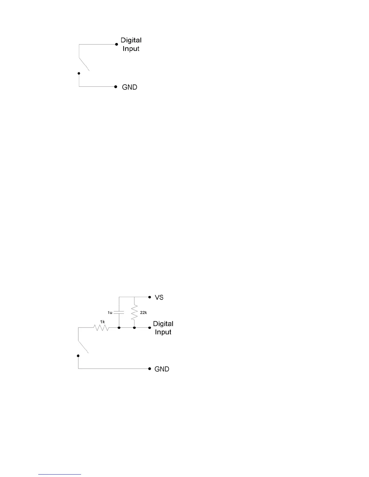
Figure 2-11. Passive Hardware Debounce
Figure 2-12 shows one possible configuration for passive hardware debounce. First, consider
the case where the 1 kΩ resistor is replaced by a short circuit. When the switch closes it
immediately charges the capacitor and the digital input sees logic low, but when the switch
opens the capacitor slowly discharges through the 22 kΩ resistor with a time constant of 22 ms.
ough for the digital input to see logic high, the
urpose of the 1 kΩ resistor is to limit the current surge
By the time the capacitor has discharged e
mechanical bouncing is done. The main p
n
28