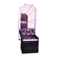
Do you have a question about the LAI Games Let’s Bounce and is the answer not in the manual?
Defines warning, caution, and note symbols and their implications for safety.
Outlines essential safety rules for operating the game, including power, grounding, and environment.
Details crucial safety steps for installing and inspecting the game to ensure player safety.
Lists all items included in the game packaging for setup and operation.
Details the game's physical dimensions, power needs, and environmental operating conditions.
Illustrates how the game unit is disassembled and packed for shipping.
Provides a visual guide to all individual parts used in the game assembly.
Guides through the first five steps of assembling the game unit, including the bounce pad.
Details steps 6 through 9 of the assembly process, focusing on the playfield frame.
Covers steps 10 to 12, involving aligning and connecting the rear stand and front cabinet.
Details steps 13 through 15, focusing on securing the playfield and plugging in connectors.
Guides through steps 16 and 17 for attaching the left and right side panels of the cabinet.
Covers steps 18 through 21 for installing the header and backboard components.
Details steps 22-24 for securing connections, powering on, and verifying functionality.
Covers final assembly steps 25-30, including acrylic panels and side covers.
Explains the core objective of the game and how players score points by hitting tiles.
Describes the gameplay flow for both Bar and Arcade modes, including bonus rounds.
Explains how attract mode provides visual and audio displays when the game is idle.
Details how to enable Coin Play and the different methods for activating Free Play mode.
Configures coin input, credits per game, and multi-stage bonus credits for coin mechanisms.
Configures bonus credits for coin mech 2, common coin pooling, and attract mode sound delay.
Sets up how error messages are displayed and enables free play mode for the game.
Defines prize types, game modes (Arcade/Bar), and scoring thresholds for bonuses.
Configures points per ticket, maximum tickets, mercy tickets, and bonus ticket/credit awards.
Tracks total coins, service credits, single/double player games, and total games played.
Monitors high scores, total tickets, average tickets, and game skips/time skipped.
Verifies functionality of lamps, displays, sounds, and lights via specific output tests.
Checks player inputs and runs mechanical tests for ticket mechs, ball gate, and dispenser.
Allows setting tiles to "offline" and managing their status for gameplay.
Lists data for the last 10 game plays, including scores and tickets paid out.
Details causes and solutions for ticket jams, coin sensor issues, and button jams.
Addresses CPU read/write errors and EEPROM communication issues with their resolutions.
Covers errors related to ball gate sensors and insufficient ball supply during gameplay.
Addresses EEPROM audit errors and issues with program settings (PSet Error).
Explains resolutions for EEPROM program setting errors and NJ firmware issues.
Identifies the main serviceable items located on the front of the game cabinet.
Details the numbered components and lamps associated with the backboard assembly.
Identifies parts of the player panel, including bounce pad and buttons.
Shows internal components like sound board, game control PCB, and ball lifter sensor.
Identifies PCBs, lightboxes, and speakers located on the rear of the cabinet.
Highlights the Fuse PCB located behind the side panel.
Details the functions of buttons on the operator panel, including navigation and service controls.
Identifies coin counters, ticket counters, and the UCL connector on the operator panel.
Explains how to access the underside of the playfield for maintenance on newer models.
Details the process of removing playfield access panels using screws and a specific sequence.
Describes the function and construction of the header, backboard, and speaker systems.
Explains the playfield's 45 tiles, sensor PCBs, and DIP switch addressing for unique IDs.
Details DIP switch patterns for configuring addresses 1 through 45.
Explains the function of game counters, operator buttons, and the volume knob.
Describes coin mechanisms, ticket mechs, playfield fuses, game board, and sound board.
Details the operation of the ball dispenser, including the lifter and gate sensors.
Covers the mains power inlet, 12VDC power supply, and fuse replacement warnings.
Details lamp types and outlines exterior and interior maintenance tasks for the game.
Lists necessary tools and guides PC setup for the firmware update process.
Details the steps for connecting the PC to the game PCB via a USB-TTL adapter.
Guides through selecting the COM port and verifying target device readability in the software.
Details selecting the target device, choosing download options like Global Erase and Verify.
Covers pressing Next, monitoring download/verify progress, and post-update checks.
Provides steps to resolve issues where no COM port is selectable in the update software.
Describes the 12VDC universal AC input power supply and voltage adjustment.
Illustrates the pinout of the 9-way Molex connector on the coin door for coin comparators.
Details the 9-pin Universal Card Link connector and its pin functions for card systems.
Describes the 4-way Molex receptacles for ticket mechanisms and default installed models.
Details signal and power connections for the middle right connection point.
Details signal and power connections for the middle left connection point.
Provides an exploded view of the main assembly with a parts list.
Lists all parts and part numbers associated with the front panel assembly.
Details components for the panel door assembly.
Details components for the base front panel assembly.
Lists parts for the coin door assembly.
Lists parts for the ticket door assembly.
Details parts for the coin plate and DBA assembly.
Lists parts for the cash box assembly.
Lists parts for the operator panel, including buttons and controls.
Lists parts related to the power supply unit.
Details all parts making up the player panel, including buttons and displays.
Lists parts for the right player panel stopper and support struts.
Lists parts for the left player panel stopper and support struts.
Lists parts for the ball gate assembly, including chute, motor, and sensor.
Lists parts for the DB box assembly, including EMI filter and housing.
Lists parts for the ball gate motor and prize dispenser arm.
Details parts for various signs, brackets, and LED boards related to the display.
Lists parts for the ball lifter mechanism, including motor and mounting.
Lists parts for the ball hopper chute and link adapter.
Lists parts for the main display panel assembly.
Lists parts for the base display panel, including LED back panels.
Details all parts for the base score panel, including displays, speakers, and brackets.
Lists parts for the Round 1 board display.
Lists parts for the Round 2 board display.
Lists parts for the right side wall assembly.
Lists parts for the left side wall assembly.
Details all components of the main playfield, including frame, pegs, and fasteners.
Lists parts for the peg assembly, including PCB, base, spacers, and screws.
Outlines operator responsibilities, unauthorized use risks, and liability for improper operation.
Details the 3-month warranty, repair obligations, and requirements for making a claim.
Provides contact details for sales, technical support, and the company website.
| Brand | LAI Games |
|---|---|
| Model | Let’s Bounce |
| Category | Arcade Game Machines |
| Language | English |
