9
1 General Information
1.3 Purpose
1.3.1 Purpose
Intended purpose VMS 4/VMS 5
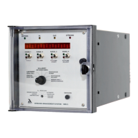
The VMS 4 as well as VMS 5 is a control unit for combustion system.
Brief description
The VMS 4 adjusts up to four control elements as a function of a control variable (generally
the burner firing rate) according to freely programmable curves.
The VMS 5 adjusts up to 5 control elements as a function of a control variable according to
freely programmable curves.
2 sets of curves (e.g. for oil or gas) can be filled as standard, with the option for 4 or 8 sets of
curves.
Examples of possible control elements:
– Combustion air damper
– Combustion air fan
– Fuel quantity
– Atomiser steam
– Re-circulation fan
– Flue gas damper
– Flue gas fan
Up to 20 points can be programmed for each channel. The display is relative between 0 and
999.
The VMS has two correction inputs for shifting the setting curves, allowing a feedback control
(e.g. O
2
trim unit) to be connected up.
Each output is freely configurable, either three-point step control element output for direct ac-
tuation of a motor or constant output (on the VMS 5 the 5th channel is always constant). The
constant output can be set to any of the following variables:
– Current signal 0 …20 mA
– Current signal 4 …20 mA
– Voltage signal 0 …10 V
The VMS 4 has two correction inputs for shifting the setting curves, allowing a feedback con-
trol (e.g. O
2
trim unit) to be connected up.
The VMS has one serial interface for remote control/ display via PC (Windows software avail-
able separately) and for connection to other system components via BUS (e.g. fault message
system, O
2
trim). Connections for Interbus-S, PROFIBUS, Modbus and CANopen are availa-
ble as options. Other BUS systems on request.
The VMS constantly monitors its own functioning and that of the control elements connected.
Each analog output (control variable and feedback or correction) is freely configurable via
plug-in cards.
Alternatively:
– Potentiometer (1 - 5k)
– Step input (DPS)
– Current signal 0/4…20 mA
– Namur transmitter
– PT100

 Loading...