32
6 Commissioning
6 Commissioning
6.1 Before Commissioning
6.1.1 Setting the Limit Switches of the Motors
As soon as the VMS is supplied with voltage, it attempts to drive the actuator motors to the
lower limit of the factory set curve. If the end-bearing's limit switches are not properly adjusted
for this, the motor may hit the actuator's mechanical stop
WARNING!
This may damage the motor or the valve.
Therefore:
Check the position of the end-bearing limit switches in the motors, taking into account the mo-
tor output shaft's travel.
If in doubt, set a shorter travel. It may be readjusted later.
6.2 Function Test
Signal on terminal 2 (Burner on) = 0
Control quantity (set point) = minimum. Turn selector
switch (2) to AUTOMATIC.
Apply voltage to VMS:
VMS performs a self-test
The display shows the VMS and its software version
briefly
Compare software version no. with sticker no.
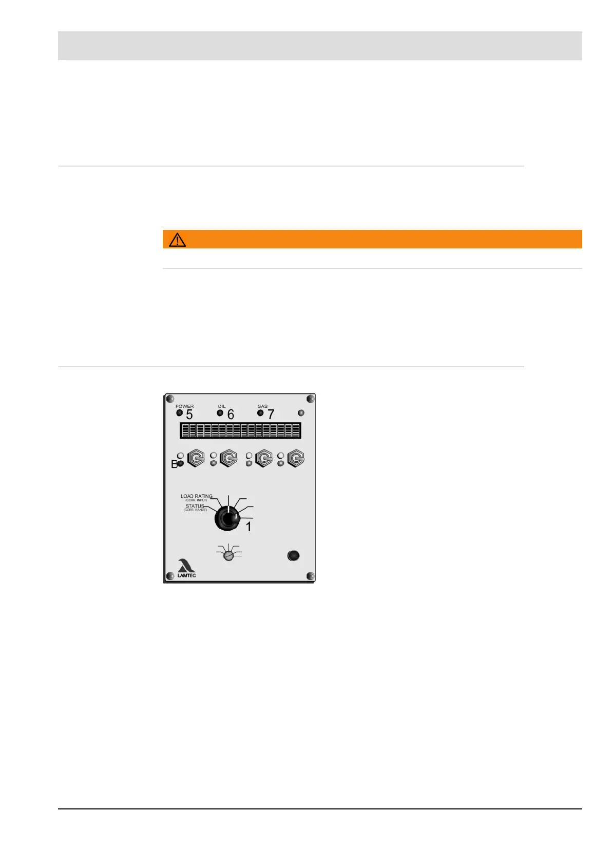
Operating display (5) lights up
Fuel LED (6 or 7) lights up
The four CLOSED LEDs (B) light up
Turn selector switch (1) to status
The display shows BURNER OFF
Turn selector switch (1) to SET POINT
the display shows external regular firing rate input of
200