18
4 Settings
4.2 Conditions On Delivery
All units are set according to the order. Settings not evident from the ID number or configura-
tion number must be indicated separately.
In particular:
Outputs
– whether continuous or three-point step
– whether 0…10 V, 0/4 … 20 mA
– position of the outputs in the event of fault
Inputs, Firing rate, Feedback
– whether potentiometer or 0/4 … 20 mA or step
– whether inputs are used double (redundant) and if so, which (possible only if the
integrated power control unit is not used)
– whether special plug-in configuration cards (Pt100, Namur transmitter) are used?
Correction input
– 0 . ..20 or 4 ... 20 mA
– Mode of operation, on which channel, upward or downward shift (modifiable only via soft-
ware)
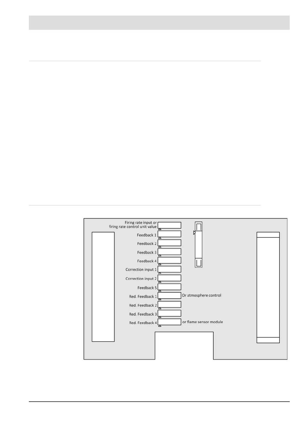
4.2.1 Assignment of Sockets in Inputs
Fig. 4-1 Backplane: Assignment of sockets to inputs