75
7 Tips and Tricks
7.3 Programming While The Burner Is Stationary
7.4 Reversing the Programming
If programming has already started and these values should not be saved, but the old curve
should be re-activated instead, then do the following:
7.5 Commissioning Equipments
When commissioning systems with the VMS it is recommended that several 5k potentiom-
eters with ready-made connections and at least 2 current transmitters are always carried (par-
ticularly where the continuous outputs are used).
The current transmitter should be adjustable in the range 0 … 20 mA. A voltage range of 0 …
10 V would also be advantageous in order to be able to simulate the continuous voltage output
of the VMS.
In addition 2 multimeters (measuring ranges: current, voltage, resistance) should be available
when commissioning.
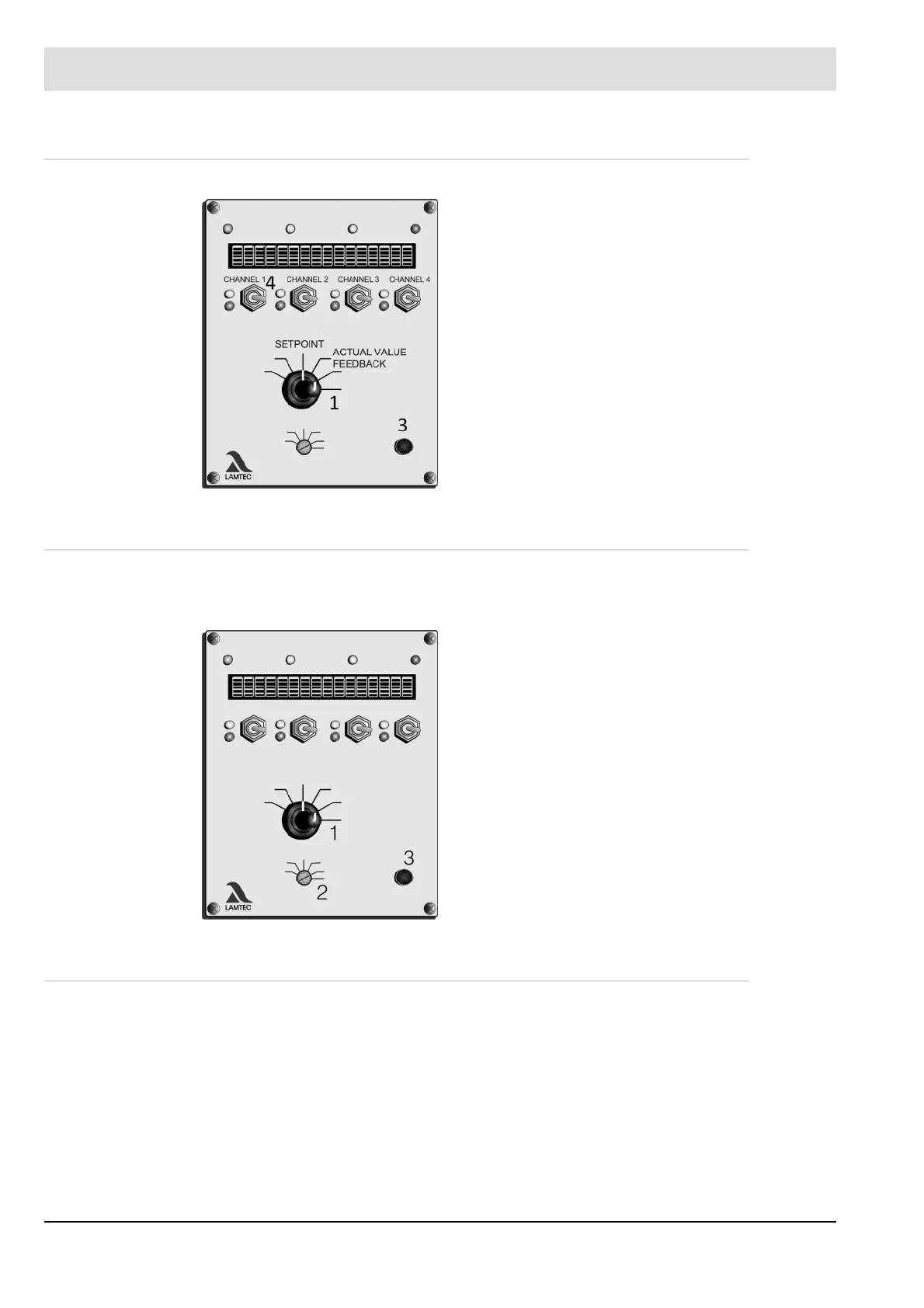
Press the ENTER (3) key.
The display shows ignition point 1.
Turn selector switch (2) to CLEAR MEMORY
Turn selector switch (1) to SETPOINT
Press ENTER (3).
the display shows ’cleared’
Turn selector switch (2) to AUTOMATIC
the old curve is valid
The unit recognises that the RAM does not contain a
valid curve that could be transferred to the EEPROM.
The last valid EEPROM curve is therefore reactivated.