34
6 Commissioning
6.4 Adjusting Control Elements
6.4.1 Operation Of Control Elements For Potentiometer Adjustment - Limit Switch Settings
NOTICE
“Setting” mode permits direct access to the control elements. It is therefore essential to follow
the safety rules specified by the burner manufacturer!
NOTICE
Adjust the control elements only when the system is stationary.
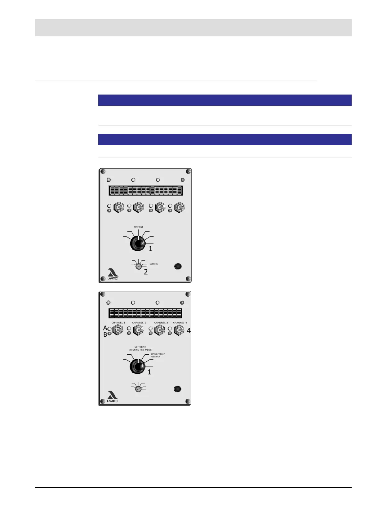
Turn selector switch (1) to ACTUAL VALUE FEED-
BACK
Turn selector switch (2) to SETTINGS
The display shows ’El’
Set "Lower stop”
Set the setpoint for channel to "0” using key (4)
Red LED (B) lights up
Actuator responds
e.g. fan runs down or motor slowly going into CLOSE
mode
Switch the limit switch to CLOSED. Adjust valve stop.
Programme the minimum r.p.m speed of frequency con-
verter
Turn selector switch (1) to "ACTUAL VALUE FEED-
BACK”
Adjust potentiometer to lower value (see table: Potenti-
ometer adjustment values)
Set "Upper stop”
Turn selector switch (1) to ’SETPOINT’
Setpoint value = 999
Switch the limit switch to ’OPEN’ - stop the flap
Check frequency converter's maximum r.p.m. speed
Turn selector switch to ACTUAL VALUE FEEDBACK.
Check upper potentiometer value (see table: Potentiom-
eter adjustment values)
Check r.p.m. speed feedback value