63
6 Commissioning
6.7.3 Correction Type 2
NOTICE
This is useful only if curve rises continuously!
WARNING!
Do not use if parts of the curve are horizontal.
WARNING!
When applying O
2
corrections, make sure that the combustion limits are observed even with
the maximum correction applied (100%).
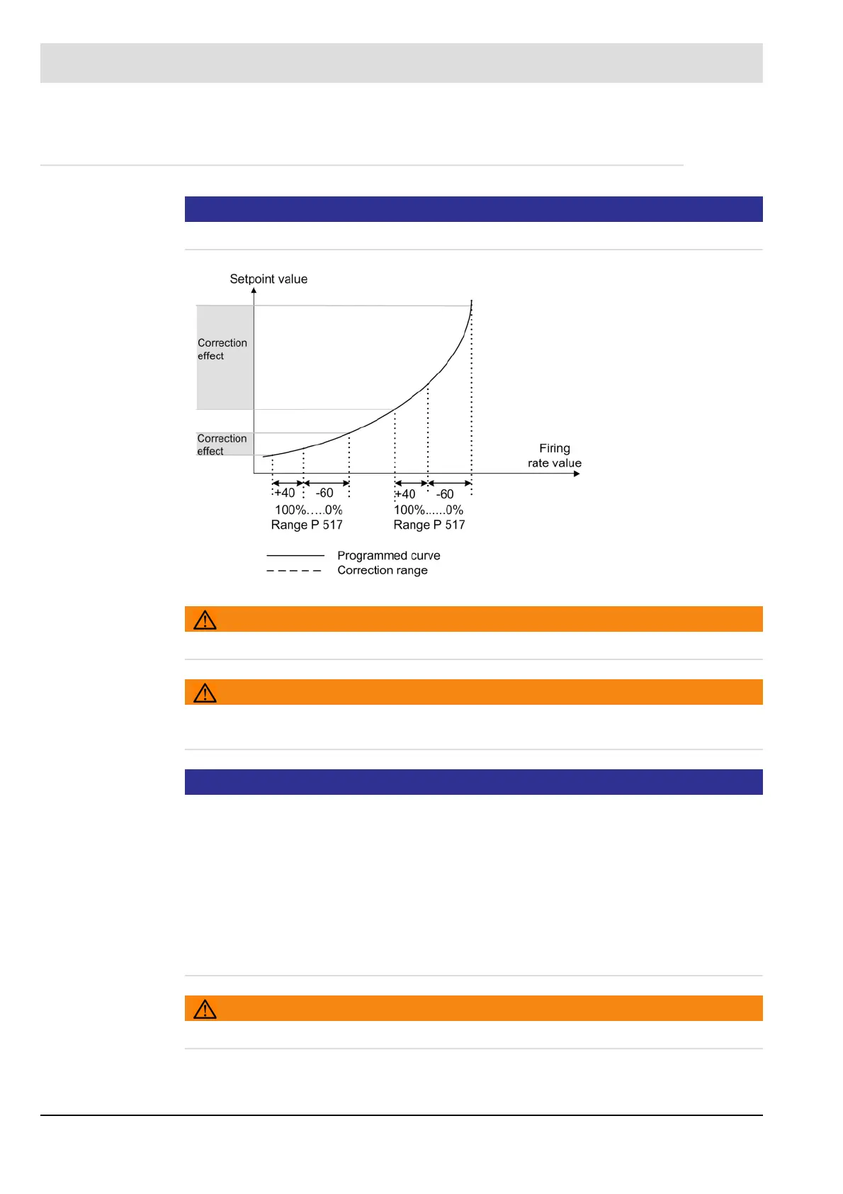
NOTICE
The correction mode indicates how the correction is intended to act. A variety of settings are
possible. Figure 1 and 2 show two typical correction modes for O
2
correction.
Type 1 is used where the correction is made on a linear control element, such as a fan fre-
quency converter. The correction is directly added to or subtracted from the setpoint value.
Type 2 is used where the correction is made on a non-linear control element such as an air
damper. Before determining the correction, account is taken of the steepness of the curve. A
flat curve results in a small correction range, whereas a steep curve give a large range.
If the correction is made to a fuel control element, the effect of the current is reversed, so that
0 mA corresponds to the smallest setpoint.
WARNING!
Do not use if parts of the curve are horizontal.