60
6 Commissioning
6.7 Correction
6.7.1 Set Correction Input
Correction signal 1: terminal 27 and 29
Correction signal 2: terminal 33 and 34
The following settings can be set by parameters in service level (level 2)
NOTICE
Correction mode and input signal are quoted in the order and are set at the factory. Any
change on site is possible only by parameter access at service level (level 2).
6.7.2 CorrectionType1
Correction type 1 is used when correction is applied through a linear control element, e.g. to
the frequency converter’s setpoint for adjusting the combustion air blower’s turning speed.
The correction is directly added to or substracted from the setpoint.
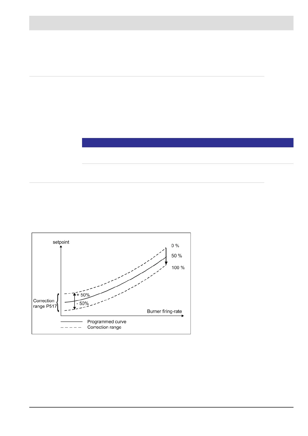
Correction mode: Affects the setpoint axis
Current signal:
Current input 1 0 … 20 or 4 … 20 mA
Current input 2 0 … 20 or 4 … 20 mA
Correction of O
2
trim with air actuator
Spread factor
Increase
Mode
Input
Neutral value
= 10
= 1.0
+60.......-40
0%...100%
60%