20
4 Settings
4.2.4 Power Supply Card
Fig. 4-4 Power supply card
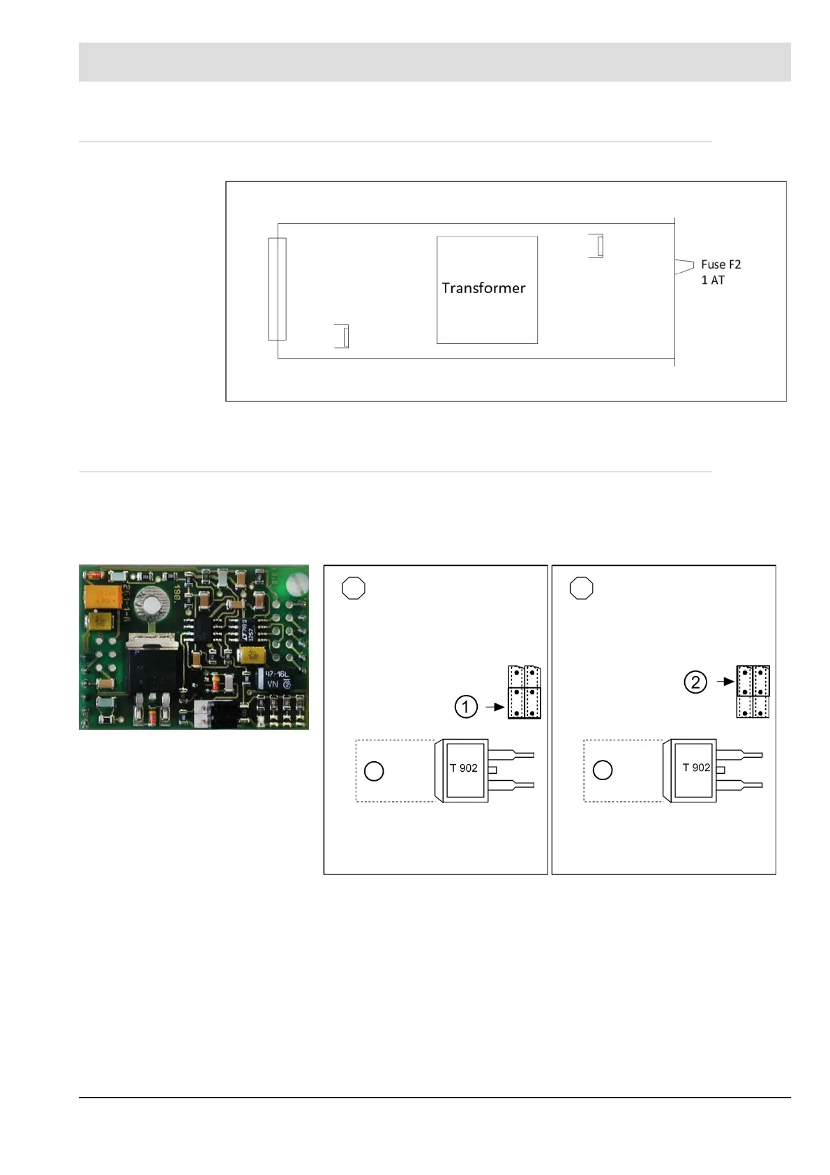
4.2.5 Plug-in P.C.Card for Continuous Output
The standard control outputs are three-point step (except for a possible 5-channel. This is
always continuous). Each TPS output can be reconfigured to make it continuous by plugging
in an additional card.
The jumpers serve only for hardware switching between current output and voltage output.The
selection of 0 or 4 … 20 mA is done through the software by parameters.
Fig. 4-5 Plug-in p.c. card for a continuous
output
Fig. 4-6 1 = Bridge - voltage output
0 ... 10V
Fig. 4-7 2 = Bridge - current output
0/4 ... 20 mA