SCS100/200/400 User Guide 2: The SCS100
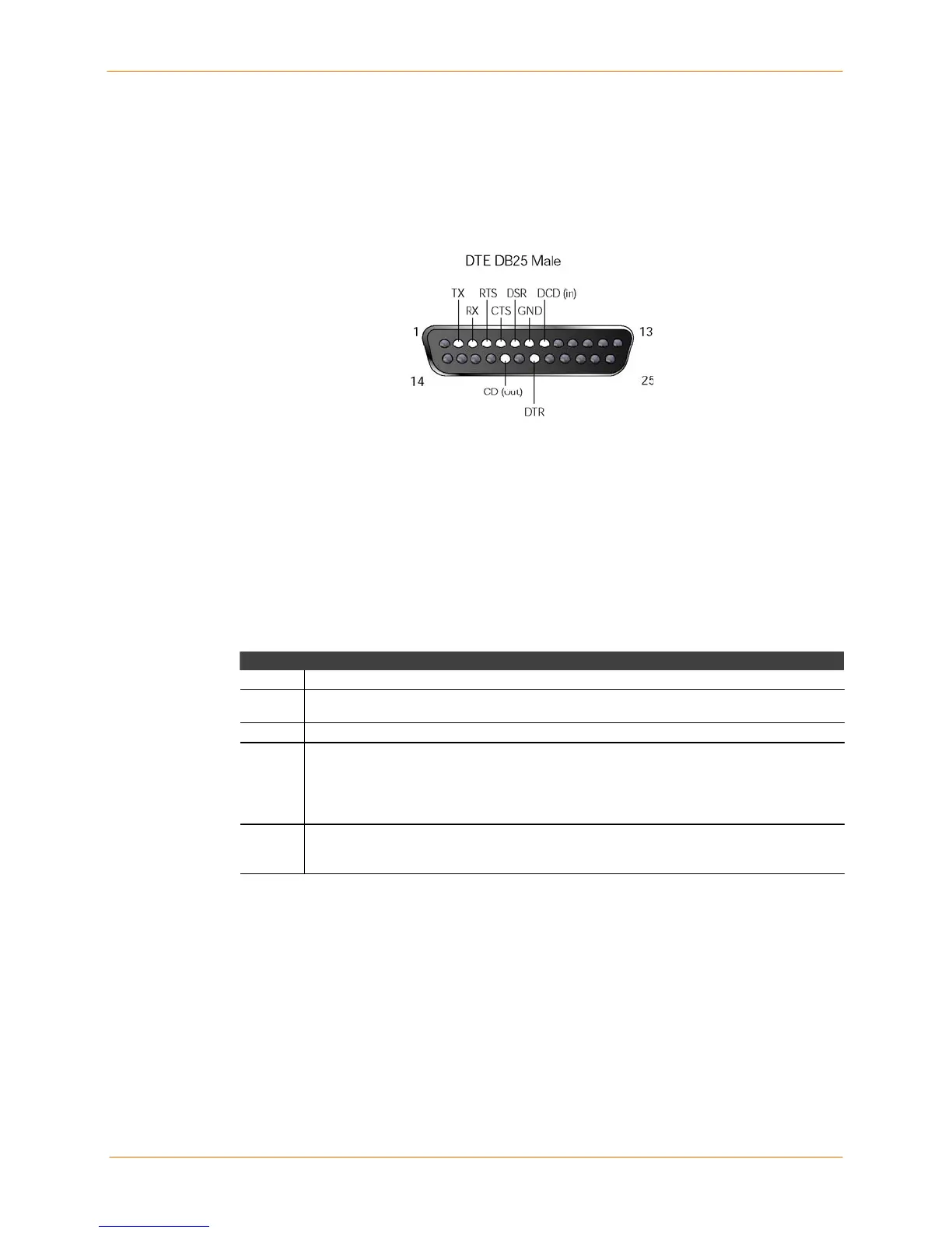
DB25 Connector Pinout
The figure below shows the pin connections of the SCS100 DB25 connector. . The
default serial port settings are 9600 baud, 8 bits, no parity, and 1 stop bit.
DB25 Serial Connector
LEDs
LEDs indicate serial port activity. The SCS100 has five LEDs on the top of the unit. A red
LED during boot mode typically signals an error, but red LED patterns during normal
operations do not signal an error. Refer to the following table for an understanding of LED
functions:
SCS100 Serial and Network LED Functions
LED Function
Power Glows green when power is supplied to the SCS.
Link
Glows green while the SCS is connected to a wired 10BASE-T or 100BASE-T
Ethernet network.
100 Glows green to indicate a 100 Mb Ethernet connection.
OK
Blinks green, yellow, or red to indicate network activity.
Green: Flashes 2-3 times per second during boot. When it flashes every 2-3 seconds,
the unit is running.
Yellow: Indicates outgoing network traffic.
Red: Indicates incoming network traffic.
Serial
Blinks green or red to indicate serial activity.
Green: Indicates outgoing serial activity.
Red: Indicates incoming serial activity.
2-2
 Loading...