SCS100/200/400 User Guide 4: The SCS400
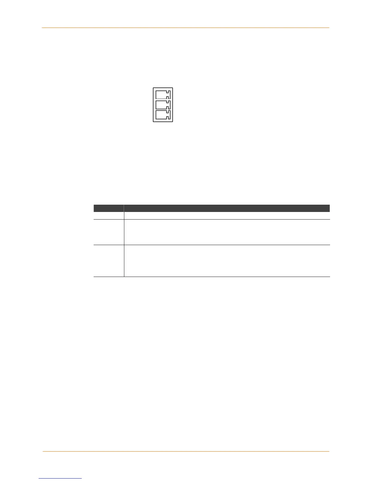
Screw Block Power
The SCS400 also has a 9-30 VDC screw block power jack.
Screw Block Power
V+
V-
Shield groun
LEDs
LEDs indicate serial port and PC card activity. The SCS400 has eight LEDs on the top of
the unit. A red LED during boot mode typically signals an error, but red LED patterns
during normal operations do not signal an error. Refer to the following tables for an
understanding of LED functions:
SCS400 Serial and Network LED Functions
LED Function
Serial (14) Blinks green to indicate serial activity.
OK
Blinks yellow, green, or red to indicate network activity.
Green: Blinks every 2 seconds when booted.
Yellow: Indicates outgoing network traffic.
Red: Indicates ingoing network traffic.
Link
Glows green or yellow while the SCS is connected to a wired 10BASE-T or
100BASE-T Ethernet network.
Off: Not connected to a wired Ethernet network.
Green: Connected to a 10Base-T network.
Yellow: Connected to either a 100Base-T or a 100BASE-FX network.
The PCC1 and PCC2 LEDs, which correspond to the top and bottom PC card slot
respectively, vary in meaning depending on what kind of card is currently installed.
4-3
 Loading...