7: 59BSetup Mode: Channel Configuration
XPort® Device Server User Guide 49
I/F (Interface) Mode
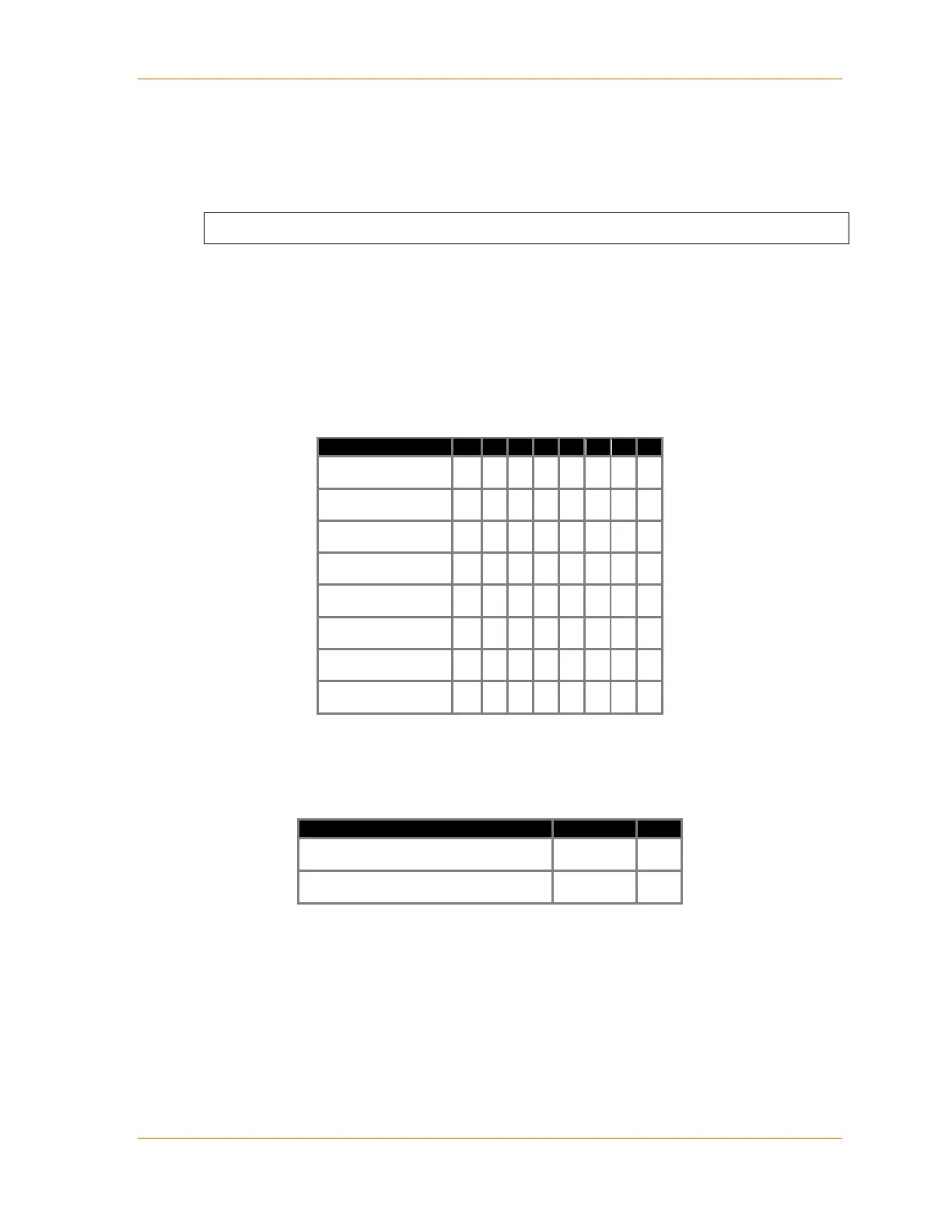
The Interface (I/F) Mode is a bit-coded byte entered in hexadecimal notation.
I/F Mode (4C) ? _
RS-232
The following table displays available I/F Mode options:
Note: All bit positions in the table that are blank represent “don’t care” bits for that particular
option, which can be set to either a 0 or 1 value.
Table 7-1. Interface Mode Options
(1) 2 stop bits are implemented by the software. This might influence performance.
The following table demonstrates how to build some common Interface Mode settings:
Table 7-2. Common Interface Mode Settings
RS-232C, 8-bit, No Parity, 1 stop bit
RS-232C, 7-bit, Even Parity, 1 stop bit
RS-485 2-Wire and RS-422 4-Wire
Additional settings for RS-422 4-wire and RS-485 2-wire are available on the XPort models.
Note: All bit positions in the table that are blank represent “don’t care” bits, for that particular
option, which can be set to either a 0 or 1 value.

 Loading...