EasyManuals Logo

Lauda Integral T 7000 W User Manual

Default Icon
108 pages
To Next Page IconTo Next Page
To Previous Page IconTo Previous Page
Page #18 background imageLoading...
Page #18 background image
Integral T process thermostats
18 Equipment description YAWE 0026 / 21/01/2019
4.8 Interfaces
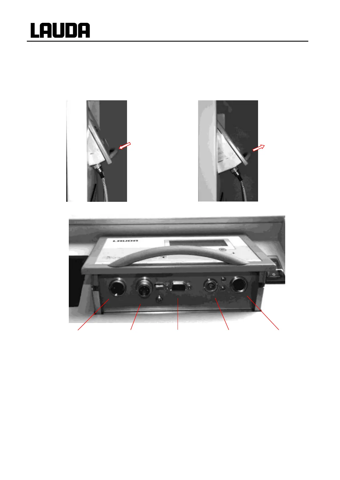
Connectors for standby contact input, fault (alarm) contact output, analogue inputs and outputs,
external Pt100 and serial RS 232/RS 485 interfaces are accessible from below after swinging out the
control unit. The control unit can be folded out to Position 2 in order to connect the sockets and then
be folded back to Position 1.
Position 1
Position 2
Standby
16N
Alarm OUT
12N
RS 232/485
65S
Pt100
10S
Standard signal
66S
Plug
Socket
Plug
Plug
Plug
EQS 048
EQD 047
EQM 042
EQS 022
EQS 057
Plug housing
EQG 026
For additional description of the interfaces see under Section 7.7 and Section 7.

Table of Contents

Questions and Answers:

Question and Answer IconNeed help?

Do you have a question about the Lauda Integral T 7000 W and is the answer not in the manual?

Lauda Integral T 7000 W Specifications

General IconGeneral
BrandLauda
ModelIntegral T 7000 W
CategoryThermostat
LanguageEnglish

Related product manuals