A
A
C
C
S
S
6
6
0
0
6
6
D
D
i
i
g
g
i
i
t
t
a
a
l
l
A
A
C
C
S
S
e
e
r
r
v
v
o
o
d
d
r
r
i
i
v
v
e
e
M
M
a
a
n
n
u
u
a
a
l
l
R
R
e
e
v
v
1
1
.
.
0
0
Tel: (86)755-26434369 14 Website: www.leadshine.com
If the motor jumps slightly and the red LED immediately turns on (flickers), then
either the motor or the encoder is wired in reversal. Open the tuning software
ProTuner and check drive status by clicking Err_check. If it’s Phase Error, then
exchange motor wires or encoder inputs and try again. If it’s Encoder Error, please
check encoder and its wirings, and then try again. If it still doesn’t work after you
followed all of the previous steps, please contact us at tech@leadshine.com.
If the red LED is off and the motor is normal, then you can start to tune the servo
with selected tool. PC based tuning software ProTuner and handheld small servo
tuning unit STU are available for the ACS606.
Tuning the Servo
A servo system is error-driven. The “Gain” of the system determines how hard the
servo tries to reduce the error. A high-gain system can produce large correcting
torques when the error is very small. A high gain is required if the output is required
to follow the input faithfully with minimal error.
A servo motor and its load both have inertia, which the servo amplifier must
accelerate and decelerate while attempting to follow a change at the input. The
presence of the inertia will tend to result in over-correction, with the system
oscillating beyond either side of its target. It’s called UNDER DAMPED status. See
Figure 11. This oscillation must be damped, but too much damping will cause the
response to be sluggish, namely cause the system to get into an OVER DAMPED
state. When we tune a servo, we are trying to achieve the fastest response with little or
no overshoot, namely get a CRITICALLY DAMPED response.
A
A
C
C
S
S
6
6
0
0
6
6
D
D
i
i
g
g
i
i
t
t
a
a
l
l
A
A
C
C
S
S
e
e
r
r
v
v
o
o
d
d
r
r
i
i
v
v
e
e
M
M
a
a
n
n
u
u
a
a
l
l
R
R
e
e
v
v
1
1
.
.
0
0
Tel: (86)755-26434369 15 Website: www.leadshine.com
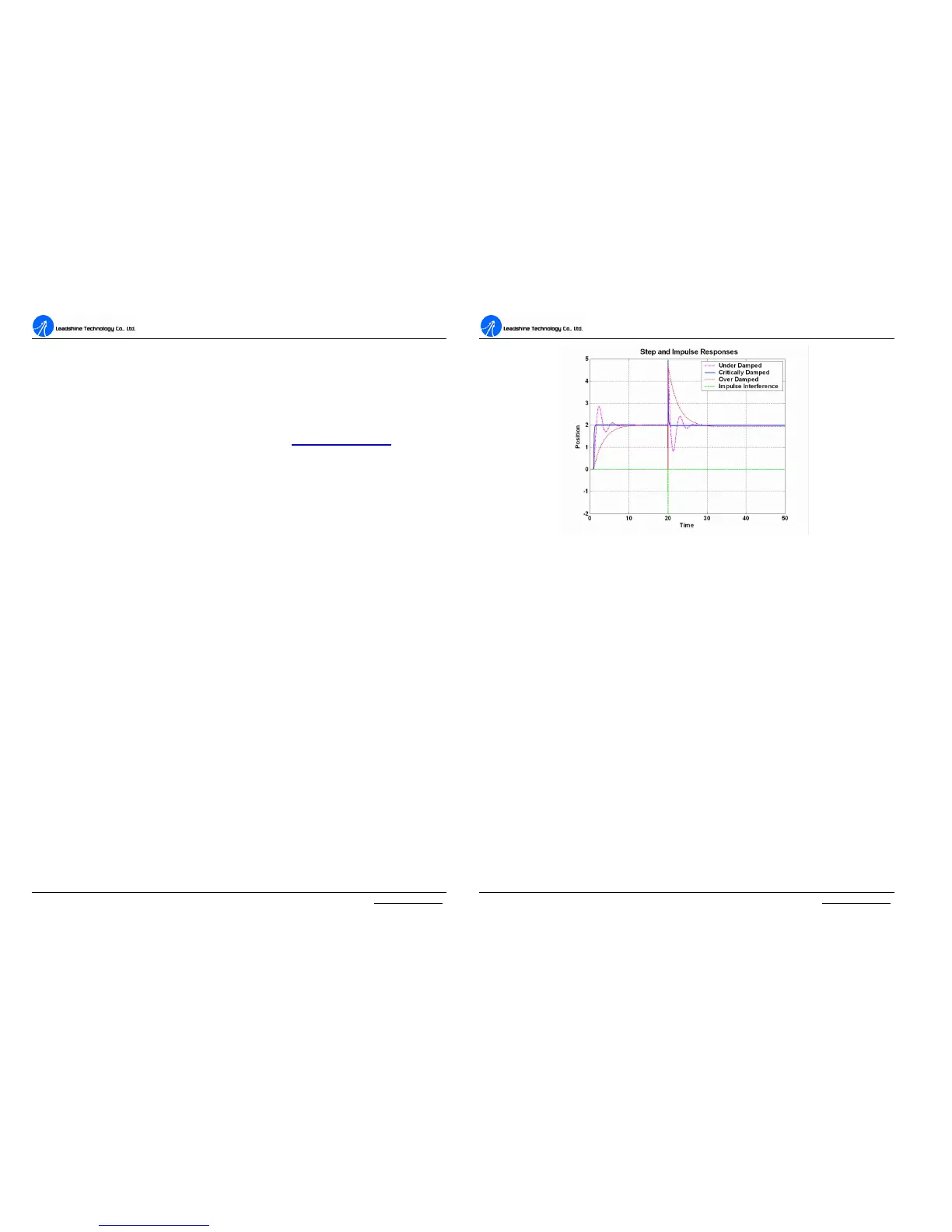
Figure 11: Step and impulse responses
As mentioned in previous contents, the ACS606 is a digital servo drive and its input
command is PUL/DIR signal. In other words, step response just exists in each step
command signal. For each step command signal is a very small movement, so
OVER SHOOT and SETTLING TIME between each step are very small, causing
you hardly can see a step response such as Figure 11, even if the SET POINT is a
very large quantity and the acceleration is very high.
However, if you try to evaluate performances of the digital servo by investigating its
position tracking-error or position following error, you may find it’s much easier
than investigating its step response. The easiest way to get a tracking-error or
position following error response is to induce an impulse load on the motor. See
Figure 11 at “time 20”.
Leadshine offers a Windows based setup software ProTuner to its customers for
evaluating servo performances. Small servo tuning unit STU (optional) is available
too, and it’s for field tuning without PC.
Tuning servo systems formed by the ACS606 can be summarized as the following
rules: