A
A
C
C
S
S
6
6
0
0
6
6
D
D
i
i
g
g
i
i
t
t
a
a
l
l
A
A
C
C
S
S
e
e
r
r
v
v
o
o
d
d
r
r
i
i
v
v
e
e
M
M
a
a
n
n
u
u
a
a
l
l
R
R
e
e
v
v
1
1
.
.
0
0
Tel: (86)755-26434369 48 Website: www.leadshine.com
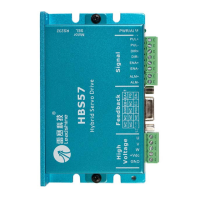
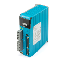
Protection Functions
To improve reliability, the drive incorporates some built-in protection functions. The
ACS606 uses one RED LED to indicate what protection has been activated. The
periodic time of RED is 5 s (seconds), and how many times the RED turns on
indicates what protection has been activated. Because only one protection can be
displayed by RED LED, so the drive will decide what error to display according to
their priorities. See the following Protection Indications table for displaying
priorities.
Over-current Protection
Protection will be activated when continuous current exceeds 20A, and RED LED
will turn on once within each periodic time (5 s).
Over-voltage Protection
When power supply voltage exceeds 63±1.5 VDC, protection will be activated and
RED LED will turn on twice within each periodic time (5 s).
Phase Error Protection
Motor power lines wrong & not connected and encoder or hall sensor feedback
signals wrong connected will activate this protection. RED LED will turn on four
times within each periodic time (5 s).
Encoder or Hall Error Protection
No encoder feedback signals or wrong encoder/hall sensor feedback signals will
activate this protection. RED LED will turn on five times within each periodic time
(5 s).
Position Following Error Protection
When position following error reaches Position Following Error Limit parameter
A
A
C
C
S
S
6
6
0
0
6
6
D
D
i
i
g
g
i
i
t
t
a
a
l
l
A
A
C
C
S
S
e
e
r
r
v
v
o
o
d
d
r
r
i
i
v
v
e
e
M
M
a
a
n
n
u
u
a
a
l
l
R
R
e
e
v
v
1
1
.
.
0
0
Tel: (86)755-26434369 49 Website: www.leadshine.com
setting in the drive, this protection will be activated. RED LED will turn on seven
times within each periodic time (5 s). Note that wrong motor connection will cause
this protection too. Please check your motor connection if this protection is activated
at the startup.
Attention: Since there is no protection against power leads (﹢,﹣) reversal, it is
critical to make sure that power supply leads correctly connected to drive. Otherwise,
the drive will be damaged instantly.
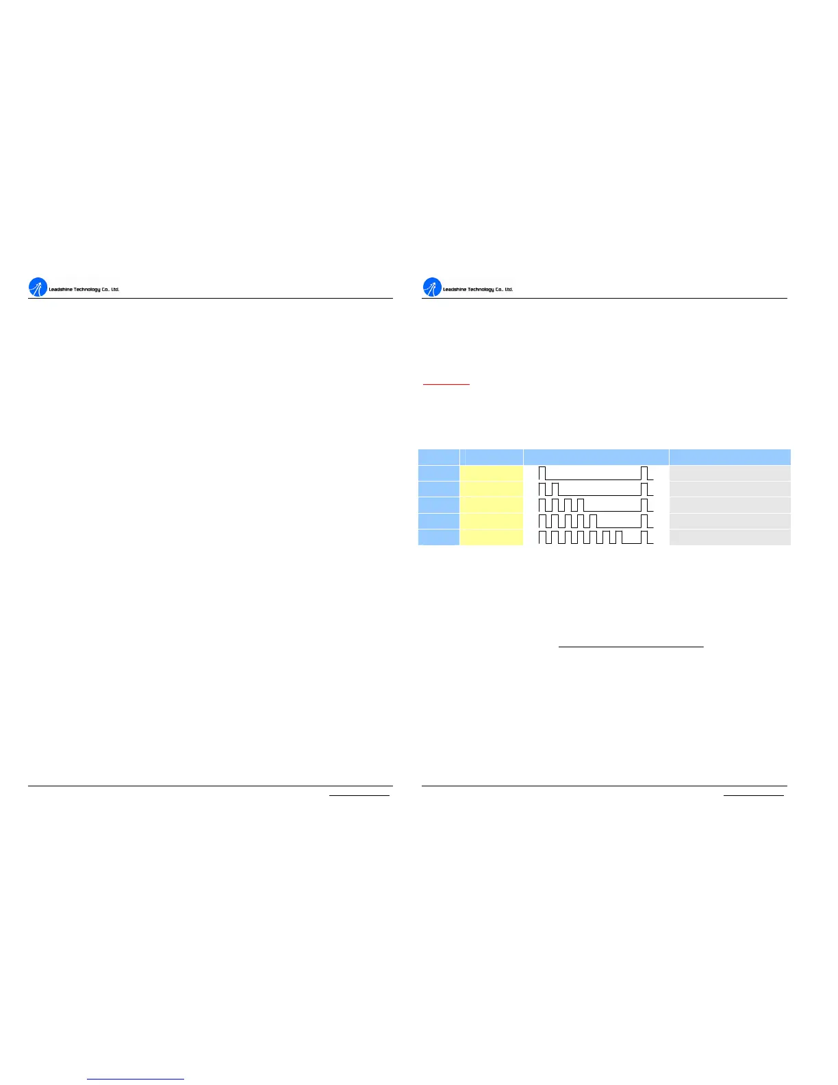
Protection Indications
Priority Time(s) of ON Sequence wave of RED LED Description
1
st
1
Over-current protection
2
nd
2
Over-voltage protection
3
th
4
Phase error protection
4
th
5
Encoder or Hall error protection
5
th
7
Position following error protection
Maximum Pulse Input Frequency
Maximum Pulse Input Frequency is the highest frequency at which the drive can
interpret encoder feedback. To convert this frequency to RPM, use the following
formula:
resolutionperPulse
FrequenceInputPulseMax
RPM
60)(
(max)
×
=