Numbers Components
CC and PDC channels.
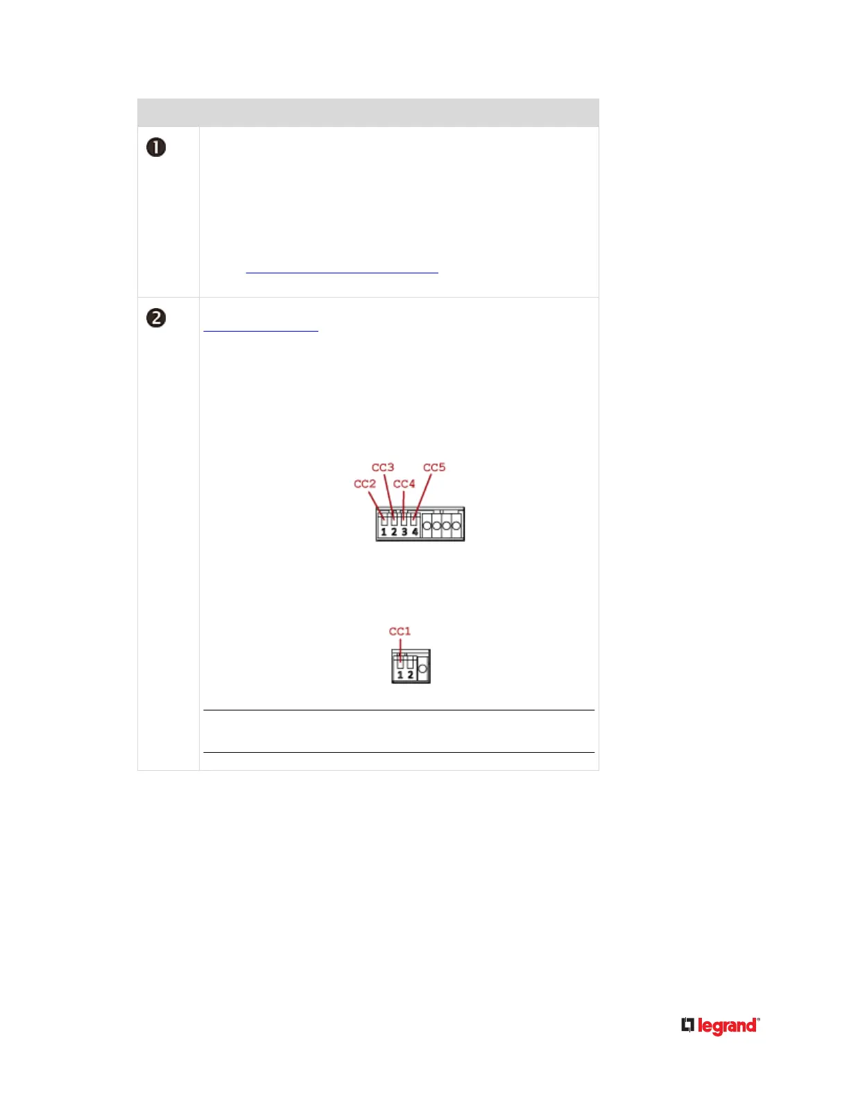
• Top row:•
Four CC channels (CC2 - CC5).
Two PDC channels (PDC1 - PDC2).
• Boom row:•
One CC channel (CC1).
See
Connecng Detectors/Actuators to DX (on page 50) for how to
connect CC sensors or DC actuators.
Dip switches for conguring the Normal state of each CC channel. See
Adjusng DIP Switches (on page 53).
• Top row:•
Dip switch 1 controls CC2.
Dip switch 2 controls CC3.
Dip switch 3 controls CC4.
Dip switch 4 controls CC5.
• Boom row:•
Dip switch 1 controls CC1.
Note: Dip switch 2 in the boom row does not control any channel
and can be ignored.
 Loading...