EasyManuals Logo

LEGRAND Tynetec Advent XT2 Installation Manual

LEGRAND Tynetec Advent XT2
50 pages
To Next Page IconTo Next Page
To Previous Page IconTo Previous Page
Page #34 background imageLoading...
Page #34 background image
Doc No. FM0814 issue 5 Page 34
IP-DECT Base Station
RPN 4 →
Repeater
RPN = XX
Repeater
RPN +64
Repeater
RPN +64
Repeater
RPN +128
Repeater
RPN +64
Repeater
RPN +128
IP-DECT Base Station
RPN 4 →
IP-DECT Base Station
RPN 4 →
IP-DECT Base Station
RPN 4 →
21. IP-DECT 6500 SYSTEM INSTALLATION
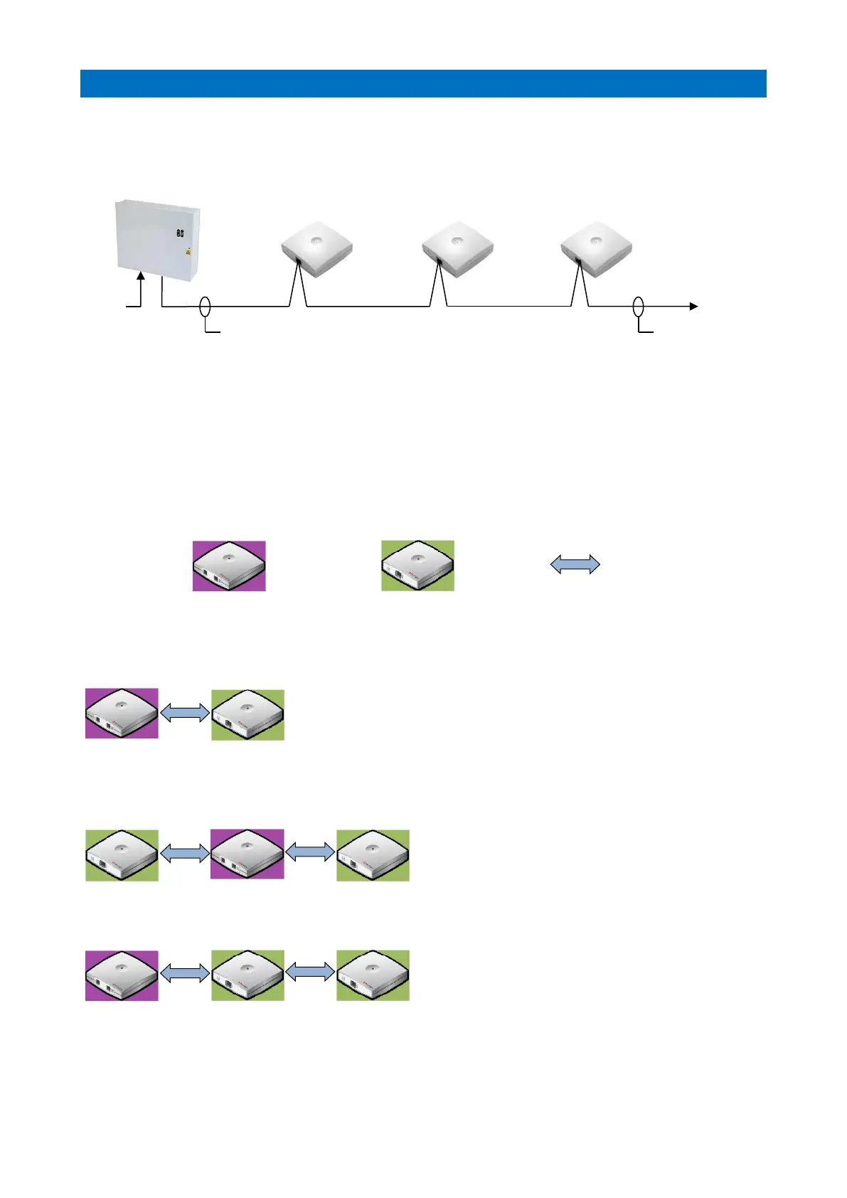
REPEATER POWER CONNECTION
Repeaters should be connected using 1.0mm pair cable; if CW1308 is being used then spare pairs can be
doubled-up and/or looped back to form a ring circuit to reduce the voltage drop if necessary.
REPEATER DEPLOYMENT RULES
A maximum of 3 Repeaters can be configured on an IP-DECT Base Station; RPN = IP Address
If you have up to 3 Repeaters on an IP-DECT Base Station they should be numbered as:
Base Station No. “X” +64, +128 and +192. The first Base Station is No. 4, second No. 5 and so on…
A maximum of 3 Repeaters can be configured in a chain
2 Repeaters cannot have the same number
See deployment examples below; RPN = the Radio Part Number
IP-DECT Base Station is shaded PURPLE Repeaters are shaded GREEN Radio handover BLUE
1 REPEATER DEPLOYMENT
1 Repeater connected directly:
2 REPEATER DEPLOYMENT EXAMPLES
2 Repeaters connected directly:
2 Repeaters connected in a chain:
4 Channel Multi Cell Repeaters
(3 per IP-DECT Base Station)
240V
AC
Battery Backed 12V DC PSU
Repeater Power Lead Colour Code
YELLOW = 12V BLACK = 0V
Use 1.0mm Cable
Max 100m

Other manuals for LEGRAND Tynetec Advent XT2

Questions and Answers:

Question and Answer IconNeed help?

Do you have a question about the LEGRAND Tynetec Advent XT2 and is the answer not in the manual?

LEGRAND Tynetec Advent XT2 Specifications

General IconGeneral
BrandLEGRAND
ModelTynetec Advent XT2
CategoryMonitor
LanguageEnglish

Related product manuals