17. Electronic Configure To Order (ECTO) Control Parameters
Page 83
PRODIGYT M2 UNIT CONTROLLER
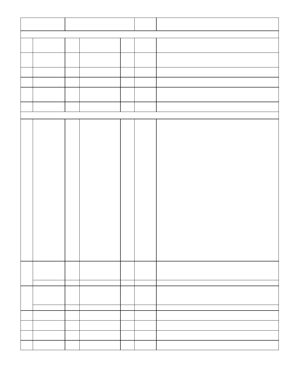
Control Parameter
No. Name
DescriptionUnits
Control Value
Min. Default Max.
Block 8 System 3 Parameters (continued)
Stg_2_SP
0
0
−0.5
.78
20
−.42
10.0
100
0.5
R:Volts
P:%
M:"w.c.
Staged 2 setpoint.
8.24
Exh_Fan_PID_I
_ Constant
0 64 255 Counts
Exhaust fan PID loop integral constant. The I constant must be limited
to 127.
Recommended setting = 12.
Stg_2_DB
0
0
64
0.25
100
1.0
P:%
L:"w.c.
Staged 2 deadband.
8.25
Exh_Fan_PID_
D_Constant
0 0 127 Counts Exhaust fan PID loop derivative constant.
8.26
Unit_Run_Op-
tions
0 1 1 Option
Add the weights for each control description to determine option.
1 − Occupied following reset until network command for OCP state is
received.
Stg_2_On_
Delay
0 0 254 A: Sec. Staged 2 on−delay.
Block 9 Optional A133 Board in GP Mode (DIP switch set to GP) Parameters
9.01
A01_control_
mode
0 0 11 Option
Analog output channel 1 control mode.
0 − No operation. Analog Output 1 off.
Enabled When Control
1− Occupied PID setpoint A
Unoccupied PID setpoint B
2− Occupied PID setpoint A
Unoccupied Staged output B
3− Occupied Staged output A
Unoccupied PID setpoint B
4− Occupied Staged output A
Unoccupied Staged output B
5− Blower On PID setpoint A
Blower Off PID setpoint B
6− Blower On PID setpoint A
Blower Off Staged output B
7− Blower On Staged output A
Blower Off PID setpoint B
8− Blower On Staged output A
Blower Off Staged output B
9 −DI2 (A133_P194−2) on PID setpoint B (1)
DI1 (A133_P194−1) on PID setpoint A (2)
Otherwise off
10−DI2 (A133_P194−2) on PID setpoint B (1)
DI1 (A133_P194−1) on Staged output A (2)
Otherwise off
11− DI2 (A133_P194−2) on Staged output B (1)
DI1 (A133_P194−1) on Staged output A (2)
Otherwise off
(1) −DI1 (A133_P194−2) doesn’t matter
(2) −DI2 (A133_P194−1) is off
9.02 AO1_SP_A
0
0
−0.5
0
127
5.00
0
2.5
255
10.0
0.5
5.0
Counts
R:Volts
M:"w.c.
N:"w.c.
Analog output channel 1 setpoint A
Stg_Output_A 0 100 100 P:% Staged output A
9.03 AO1_SP_B
0
0
−0.5
0
127
5.00
0
2.5
255
10.0
0.5
5.0
Counts
R:Volts
M:"w.c.
N:"w.c.
Analog output channel 1 setpoint B
Stg_Output_B 0 100 100 P:% Staged output B.
9.04
AO1_Startup_
Value
0
0
50
50
100
100
Counts
P:%
Analog output channel 1 startup value. Value set to Analog Output
during the optional startup time delay set by ECTO 9.05.
9.05
AO1_Startup_
Delay
0
0
0
0
250
500
Counts
A:Sec.
Analog output channel 1 startup delay. Optional time delay before PID
loop starts.
9.06
AO1_Min_ Out-
put
0
0
20
20
100
100
Counts
P:%
Analog output channel 1 minimum output.
9.07
AO1_ Max_
Output
0
0
100
100
100
100
Counts
P:%
Analog output channel 1 maximum output.
table continued on next page