19. Sequence of Operation
Page 89
PRODIGYT M2 UNIT CONTROLLER
19. Sequence of Operation
19.1. Unit Controller Control Modes
Unit Controller can operate in several different control modes. The selection of these control modes will depend upon sever-
al factors:
S Unit type − constant air volume (CAV) or variable air volume (VAV) with supply fan variable frequency drive.
S Zoning application (single zone, bypass zoning or zoning)
S Which device will control rooftop unit staging and unit operation (thermostat / third party unit controller or the Unit Con-
troller)
S The desired level of unit heating and cooling staging (2 heat / 2 cool or 4 heat / 4 cool)
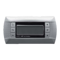
19.1.1. Unit Controller In Zone Sensor Mode
When in the zone sensor mode, the unit controller can provide up to four stages of mechanical heating and cooling opera-
tion. Constant volume units in single zone applications can use this control mode. The zone sensor will provide space tem-
perature information to the unit controller. The unit controller houses all space temperature setpoints and controls all rooftop
unit staging and general operation. The unit controller also determines unit error codes, provides diagnostic information and
maintains safe operation limits. It is important to note that scheduling and/or setpoint control requires the use of a L Connec-
tion Network Control Panel.
HUM
AI1
TMP
D01 D02
DI1
DI3DI2
DI4
24VAC
R
C
24VAC
C
24VAC
THERMOSTAT
G
OCP
C
G
W1 Y1
W2
Y2
O
L
R
SENSOR
OUTPUTSSENSOR
IAQ
SMOKE
R
HUMIDISTAT
INPUTS
R R
C
2
FOR HUMIDITROL OR
SUPERMARKET REHEAT OPTION
2
RH SENSOR ZONE SENSOR
Figure 36. Constant Air Volume Unit in Single Zone Application
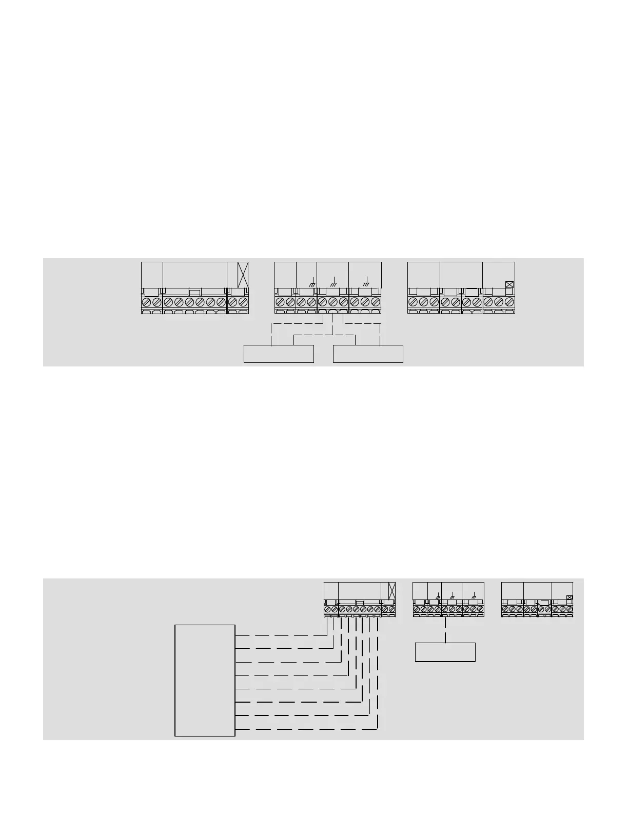
19.1.2. Unit Controller In Thermostat Mode
When in the thermostat mode, the unit controller can provide up to two stages of mechanical heating and cooling operation.
Constant volume units in either single zone or bypass zoning applications can use this control mode. To operate correctly, a
Lennox or third−party thermostat or unit control must provide the following wiring connections to the unit controller:
1. Ventilation demand
2. Occupied demand
3. Heating demand one
4. Heating demand two
5. Cooling demand one
6. Cooling demand two
In this configuration, either the thermostat or unit control will control the rooftop unit staging and general operation. The unit
controller functions primarily to determine unit error codes, provide diagnostic information and maintain safe operation lim-
its.
HUMAI1
D01
TMP
D02
DI1
DI4
DI2
DI3
24VAC
THERMOSTAT
R C
W1
G W2 Y2Y1
OUTPUTS
SENSOR
SENSOR
24VAC
R
C
IAQ
INPUTS
SMOKE
24VAC
RRC R
C
HUMIDISTAT
G
OCP
O
L
1
SEE AFTERMARKET CONTROLLER INSTALLATION
INSTRUCTIONS FOR WIRING INFORMATION.
2
FOR HUMIDITROL OR SUPERMARKET REHEAT OPTION.
1
AFTERMARKET
RTU CONTROLLER
2
RH SENSOR
24VAC
COMMON
VENTILATION DEMAND
HEATING DEMAND ONE
HEATING DEMAND TWO
COOLING DEMAND ONE
COOLING DEMAND TWO
OCCUPIED DEMAND
Figure 37. Constant Air Volume Unit In Single Zone Application