19. Sequence of Operation
Page 90
506457−01 05/10
AI1
D01
HUM
TMP
D02
DI1
DI2 DI3
DI4
SENSOR
IAQ
Y2
THERMOSTAT
24VAC
C
R
W1
W2 Y1GRC
24VAC
HUMIDISTAT
OUTPUTSSENSOR INPUTS
24VAC
R C
SMOKE
R R
C
G
OCP
O
L
1
AFTERMARKET
RTU CONTROL-
LER
1
SEE AFTERMARKET CONTROLLER INSTALLATION
INSTRUCTIONS FOR WIRING INFORMATION.
24VAC
COMMON
VENTILATION DEMAND
HEATING DEMAND ONE
HEATING DEMAND TWO
COOLING DEMAND ONE
COOLING DEMAND TWO
OCCUPIED DEMAND
1
BYPASS
DAMPER
1
SUPPLY STATIC
PRESSURE
SENSOR
1
OPTIONAL
BUILDING STATIC
PRESSURE SWITCH
OR SENSOR
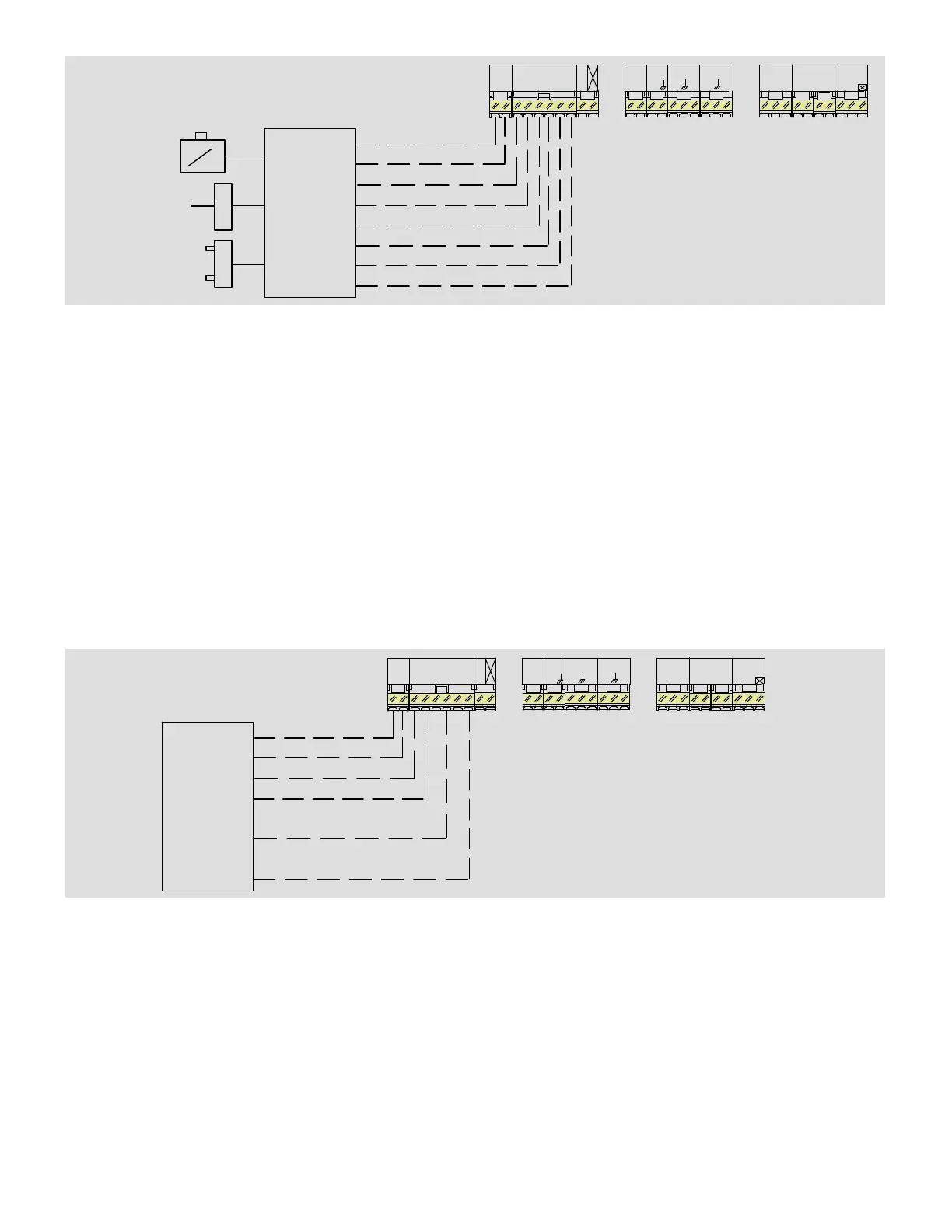
Figure 38. Constant Air Volume Unit in Bypass Zoning Application
When in thermostat mode and configured for discharge air temperature control, the unit controller can provide up to four
stages of mechanical heating and cooling operation. Variable air volume units using a variable frequency drive on the supply
fan and operating in a zoning application must use this control mode. Although not as common, constant volume units in
either single zone or bypass zoning applications may also use this control mode. To operate correctly, a Lennox or third−
party thermostat or unit control must provide the following wiring connections to the unit controller:
1. Ventilation demand
2. Occupied demand
3. Heating demand
4. Cooling demand
In this control mode the unit controller will control all cooling and heating staging to maintain the the discharge air tempera-
ture setpoints set in the unit controller (typically 55°F for cooling and 110°F for heating). A third−party unit control, or a ther-
mostat can provide these inputs to the unit controller. For example, if the unit control passes along a demand for cooling then
the unit controller will activate the refrigeration system and increase or decrease cooling stages to maintain the discharge
supply air temperature setpoint. In this mode, the unit controller will also maintain the supply duct static pressure by directly
controlling the supply fan variable frequency drive. Along with providing control of the rooftop unit, the unit controller will also
provide error codes and diagnostic information.
AI1
D01
HUM
TMP
D02
DI1
DI2 DI3
DI4
SENSOR
IAQ
Y2
THERMOSTAT
24VAC
C
R
W1
W2 Y1GRC
24VAC
HUMIDISTAT
OUTPUTSSENSOR INPUTS
24VAC
R C
SMOKE
R R
C
G
OCP
O
L
AFTERMAR-
KET RTU CON-
TROLLER OR
THERMOSTAT
24VAC
COMMON
VENTILATION DEMAND
HEATING DEMAND
COOLING DEMAND
OCCUPIED DEMAND
Figure 39. Variable Air Volume Unit in Zoning Application
19.1.3. Operations Common to All Rooftop Units
The following sequence of operation information applies to all Energence rooftop units regardless of unit controller control
mode, unit type or zoning application.
19.1.3.1. Heating Operation (Modulating Gas)
The Energence unit features two separate gas burner sections, each with a modulating gas valve and a shut−off valve. The
modulating gas heat section can provide continuous operation from 25−100% of total heat capacity. Upon receiving a heat-
ing demand, the unit controller will instruct the modulating gas unit to maintain a discharge air temperature setpoint (default
110°F). The unit maintains this setpoint by feeding information from a discharge air temperature sensor located in the supply
duct back to the unit controller. Based on this information, the unit controller increases or decreases gas heat output to
maintain the desired heating setpoint.