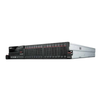
Table 4. Components in the front view
1 Front operator panel buttons and LEDs
6 “XCC system management port (1GbE RJ-45)” on
page 19
2 7mm 2.5-inch drive bays (bays 0 to 3) 7 “2.5GbE RJ-45 connectors” on page 19
3 “USB 3.2 Gen 1 Type-A connectors” on page 19 8 “10/25GbE SFP28 connectors” on page 19
4 “USB 3.2 Gen 1 Type-C connector (supporting
display)” on page 19
9 15mm 2.5-inch drive bays (bays 0 to 1)
5 “USB 2.0 Gen 1 Type-C connector with Lenovo
XClarity Controller (XCC) management” on page 19
10 “1GbE RJ-45 connectors” on page 19
1 Front operator panel buttons and LEDs
For more information about the front operator panel buttons and LEDs, see
“Front operator panel LEDs” on
page 187
.
Notes:
• When the shipping bracket is installed, the front operator panel is not accessible.
2 9 2.5-inch drive bays (bay 0 to 3)
• Install 2.5-inch drives or drive bay fillers to these bays (see
“Install a hot-swap drive” on page 88).
• For more information about the drive LEDs, see
“Drive LEDs” on page 187.
3 4 5 6 7 8 10 Front I/O Module
Notes:
• The following illustrations show the front I/O module of ThinkEdge SE350 V2.
• Depending on the configuration, the front I/O module is determined by one of the following networking
options:
– 10/25GbE I/O module
– 1GbE I/O module
• For more information about LAN port LEDs, see
“LAN port LEDs” on page 189.
Figure 4. Front I/O of 10/25GbE I/O module
Figure 5. Front I/O of 1GbE I/O module
Table 5. Components in the front I/O module
3 “USB 3.2 Gen 1 Type-A connectors” on page 19 7 “2.5GbE RJ-45 connectors” on page 19
4 “USB 3.2 Gen 1 Type-C connector (supporting
display)” on page 19
8 “10/25GbE SFP28 connectors” on page 19
18 ThinkEdge SE350 V2 User Guide

 Loading...


