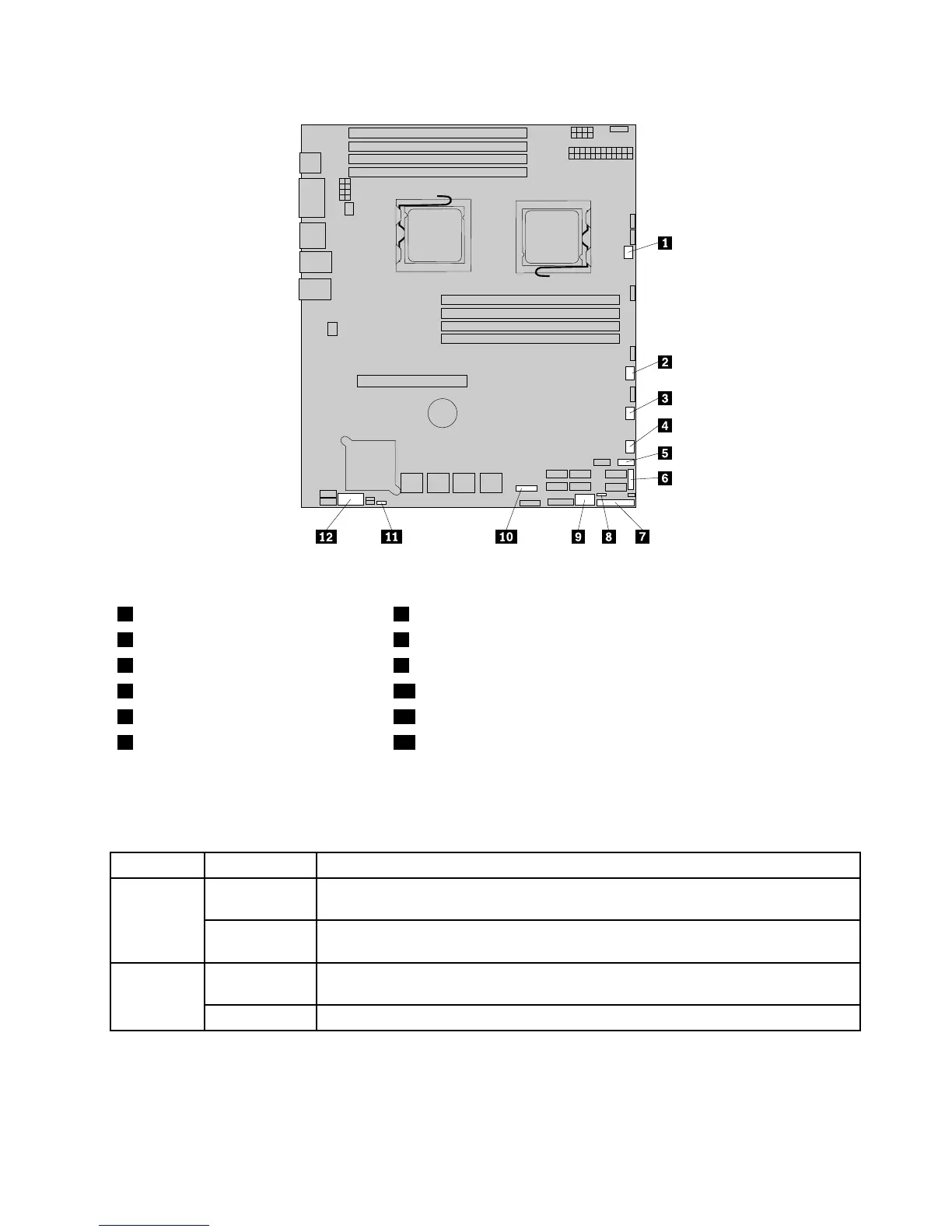
Figure6.Locatingotherconnectorsonthesystemboard
1Systemfan1connector7J35(forfrontcontrolcable)
2Systemfan2connector8JP1(clearCMOS)
3Systemfan3connector9USB2connector
4Systemfan4connector10J21(SGPIOconnectorforonboardSASport5-8)
5FrontUSBconnector11JP7(setonboardSAS)
6J51(SGPIOconnectorforonboard
SASport1-4)
12J16(COM2connector)
Thefollowingtableintroducesthejumperswitchesonthesystemboard.
Table7.Jumpersettings
JumperPositionDescription
Pins1-2
Thedefaultpositionatwhichthejumperisplacedonpins1-2duringthenormal
operationofthesystem.
JP1:Clear
CMOS
Pins2-3
Ifthejumperisplacedonpins2-3,whenthejumperismovedbacktothedefault
position,thesettingsofCMOSwillbeclearedautomaticallyatthenextstartup.
Pins1-2
Thedefaultpositionatwhichthejumperisplacedonpins1-2duringthenormal
operationofthesystem.TheonboardSAScontrollerisenabled.
JP7:Set
Onboard
SAS
Pins2-3
Ifthejumperisplacedonpins2-3,theonboardSAScontrollerisdisabled.
Note:BeforeclearingtheCMOS,turnofftheserveranddisconnectthepowercord.Movethejumperfrom
pins1-2topins2-3.Waitmorethanveminutesandthenmovethejumperbacktothenormalposition
(pins1-2)toclearCMOS.
Chapter4.Locatingparts,controls,LEDs,andconnectors15