4 Memory modules 9 3.5-inch hard disk drive
5 Power supply
assembly
10 Left handle of the chassis
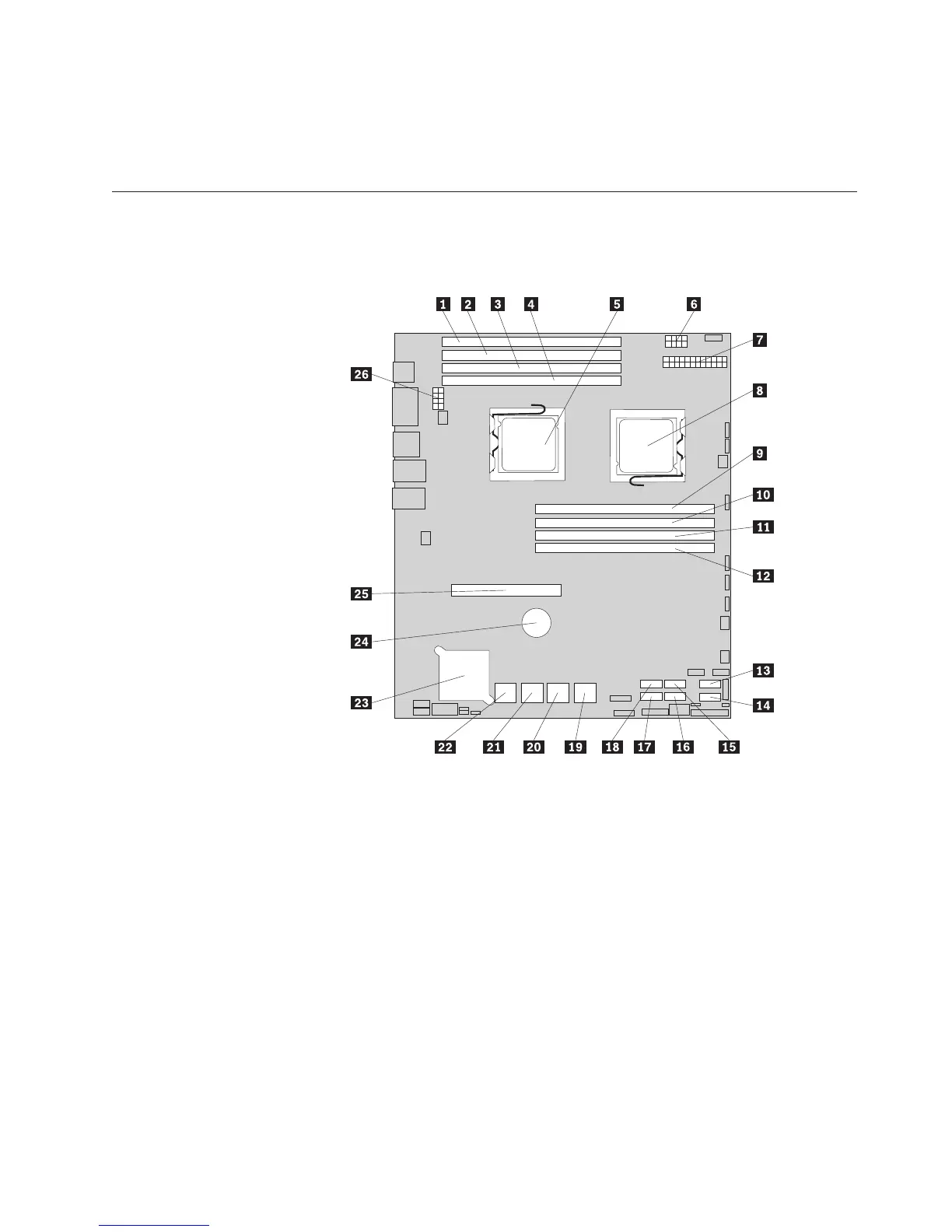
Locating parts on the system board
Figure 5 and Figure 6 on page 16 show the locations of the parts on the system
board.
1 Memory slot (CPU1 DIMM CHC0) 14 SATA connector 1
2 Memory slot (CPU1 DIMM CHB0) 15 SATA connector 2
3 Memory slot (CPU1 DIMM CHA0) 16 SATA connector 3
4 Memory slot (CPU1 DIMM CHA1) 17 SATA connector 5
5 Microprocessor (CPU1) 18 SATA connector 4
6 Power connector 2 (for CPU0) 19 SAS connectors (top: SAS 1; bottom: SAS 0)
7 24-pin power connector for the
system board
20 SAS connectors (top: SAS 3; bottom: SAS 2)
8 Microprocessor (CPU0) 21 SAS connectors (top: SAS 5; bottom: SAS 4)
9 Memory slot (CPU0 DIMM CHA1) 22 SAS connectors (top: SAS 7; bottom: SAS 6)
10 Memory slot (CPU0 DIMM CHA0) 23 Onboard 1068E SAS RAID controller
11 Memory slot (CPU0 DIMM CHB0) 24 System board battery
12 Memory slot (CPU0 DIMM CHC0) 25 PCI Express x16 card slot (for a riser card)
13 SATA connector 0 26 Power connector 3 (for CPU1)
Figure 5. Locating major parts on the system board
Chapter 4. Locating parts, controls, LEDs, and connectors 15