62
V340-17IWL Hardware Maintenance Manual
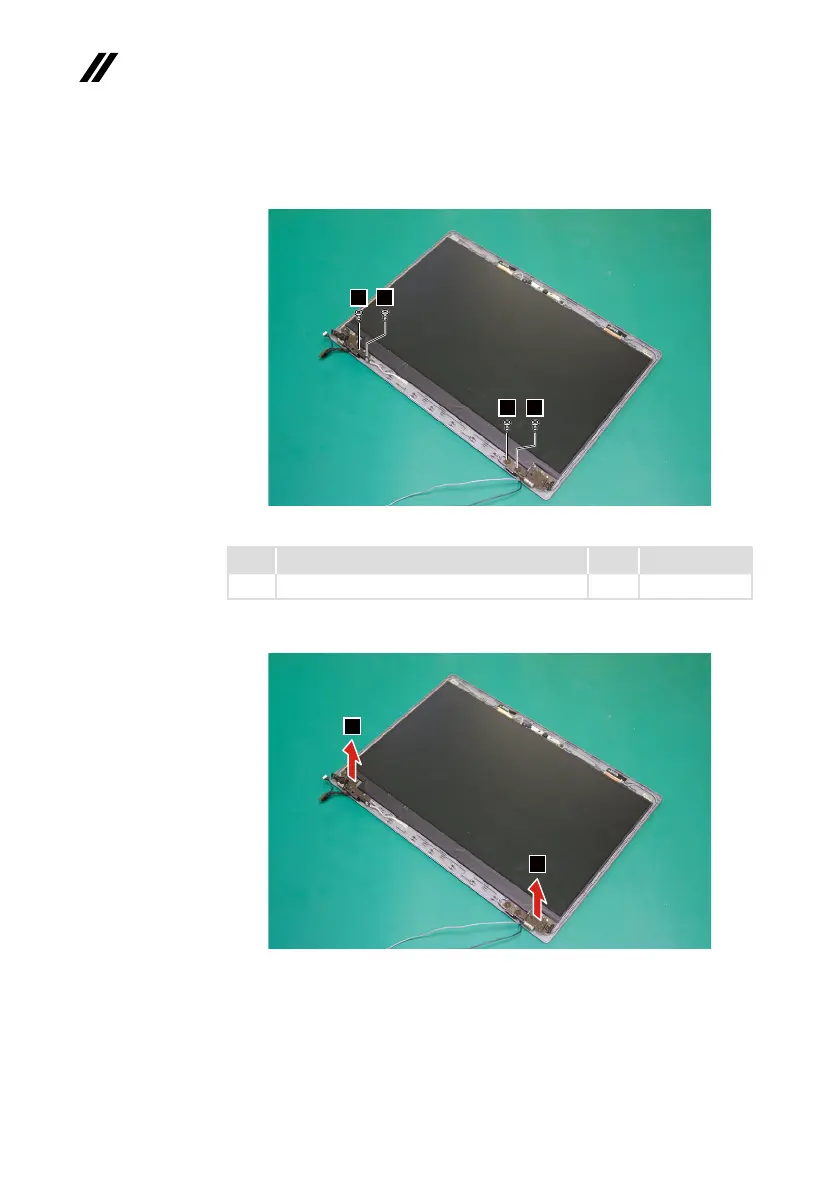
Step7: Removethescrews
6
.
6
6
6
6
Figure 33. Remove the screws
Step Screw (quantity) Color Torque
7
M2.5×2.5mm,Phillips-head,nylok-coated(4) Black 3+/-0.3kgf/cm
Step8: RemovetheLCDhingesinthedirectionshownbyarrows
7
.
7
7
Figure 34. Remove the LCD hinges
When installing:Makesurethattheconnectorisattachedrmlyandthatyou
donotpinchtheantennacableswhenyouattachtheLCDassembly.Routethe
LCDcablealongthecableguides.