Electrical installation
Control terminals
6
l
33
LDEDS−CCU210B EN 4.0
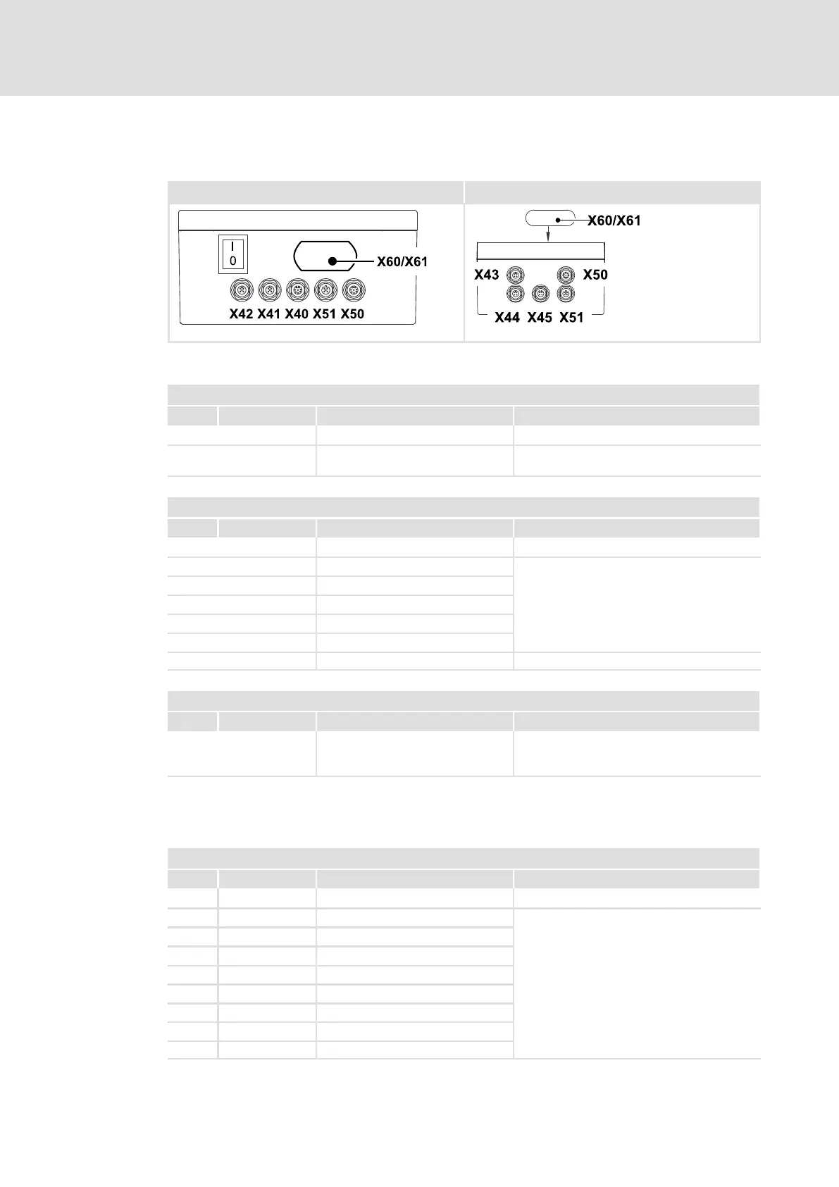
6.5 Control terminals
Device in a power range of 1.5 kW and 2.2 kW Devices in a power range of 0.75 kW
CCU210_002E CCU_210_002G
Common control terminals
X50 − external data memory
Pin Signal Description Data
EXMID1 Connector: socket, 8−pole, M12
Connection of external data
memory
Max. 2 kB Depending on the application
X51 – anti−collsion sensor for RS485 SensoPart forward travel
Pin Signal Description Data
Connector: socket, 5−pole, M12, B−coded
1 +24V Supply
2 A RS485 signal A
3 GND Reference potential
4 B RS485 signal B
5 n. c. Not assigned
− Shld Shield Applied to the connector housing
X60, X61 – CAN system bus connection
Pin Signal Description Data
Two CAN system bus terminals for
parameter setting and
configuration
Connector: RJ45
Control terminals for devices in a power range of 1.5 kW and 2.2 kW
X40 − digital inputs DIN3 ... DIN7/digital output DOUT2
Pin Signal Description Data
Connector: socket, 8−pole, M12
1 DIN3 Digital input 3 HIGH +16 .... +26.5 V DC
2 DIN4 Digital input 4 LOW 0 ... +4 V
3 DIN5 Digital input 5 4 mA Current per input for 24 V DC
4
DIN6 Digital input 6
max.
200 mA
Permissible current loading per
output
If inductive loads are switched,
use a freewheeling diode as
close to the inductive load as
possible!
5 +24V DC Supply
6 DIN7 Digital input 7
7 GND Reference potential
8 DOUT2 Digital output 2