Electrical installation
Control terminals
6
l
34
LDEDS−CCU210B EN 4.0
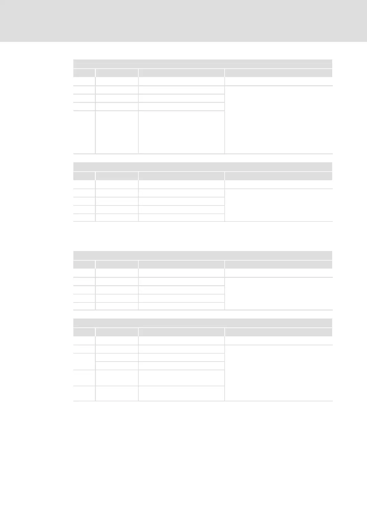
X41 − digital input DIN2 / digital output DOUT1
Pin Signal Description Data
Connector: socket, 4−pole, M12
1 +24V DC Supply HIGH +16 .... +26.5 V DC
2 DOUT1 Digital output 1 LOW 0 ... +4 V
3
GND Reference potential 4 mA Current per input for 24 V DC
4
DIN2 Digital input 2 max.
200 mA
Permissible current loading per
output
If inductive loads are being
switched, freewheeling diodes
are required. Place the diodes
as close to the inductor load as
possible!
X42 − digital inputs DIN1/DIN8
Pin Signal Description Data
Connector: socket, 4−pole, M12
1 +24V DC Supply HIGH +16 .... +26.5 V DC
2 DIN8 Digital input 8 LOW 0 ... +4 V
3 GND Reference potential
4 mA Current per input for 24 V DC
4 DIN1 Digital input 1
Control terminals for devices in a power range of 0.75 kW
X43 − digital inputs DIN1/DIN2
Pin Signal Description Data
Connector: socket, 4−pole, M12
1 +24V DC Supply HIGH +16 .... +26.5 V DC
2 DIN1 Digital input 1 LOW 0 ... +4 V
3
GND Reference potential 4 mA Current per input for 24 V DC
4 DIN2 Digital input 2
X44 − digital inputs DIN3/DOUT1 − DIN4
Pin Signal Description Data
Connector: socket, 4−pole, M12
1 +24V DC Supply HIGH +16 .... +26.5 V DC
2
1)
DIN3 Digital input 3 LOW 0 ... +4 V
DOUT1
Digital output 1 4 mA Current per input for 24 V DC
3 GND Reference potential
max.
200 mA
Permissible current loading per
output
If inductive loads are being
switched, a spark suppressor
must be used at the output!
4 DIN4 Digital input 4
1)
DIN/DOUT cannot be used at the same time!