Device description
Overview
3
l
13
LDEDS−CCU210B EN 4.0
3.2 Overview
Power 0.75 kW
CCU210_002H
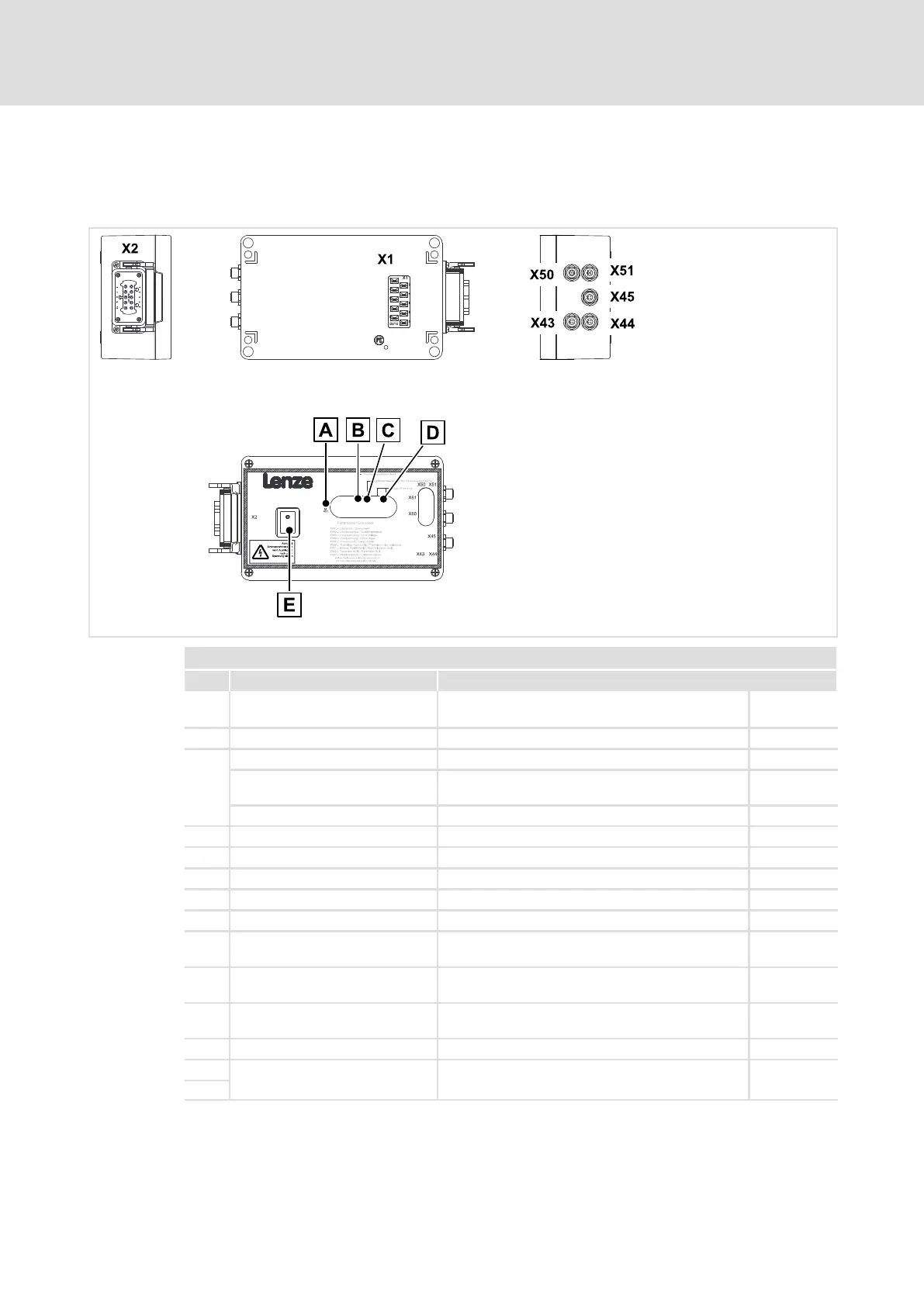
Operational control and connections
Pos. Function Description
0 Important fault messages Short description of the most important fault
messages
^ 81
1 Status display of device (LED) Readiness for operation, error ^ 78
2
Infrared receiver ...
... for infrared data transmission
(IrDA)
Parameter setting, manual operation and status
enquiries via PDA
^ 65
... for infrared remote control (IrRC) Manual operation via infrared remote control ^ 68
3 4−digit 7−segment display Status display, error messages, warning signals ^ 79
4 On/Off switch Software deactivation, acknowledgement of errors
X1 Mains connection Connector: flat connector, 10−pole ^ 31
X2 Motor connection Connector: socket, Harting HAN−10B, 10−pole + PE ^ 32
X43 Digital inputs DIN1/DIN2 Connector: socket, 8−pole, M12 ^ 34
X44 Digital inputs DIN3/DIN4
Digital output DOUT1
Connector: socket, 4−pole, M12 ^ 34
X45 Digital inputs DIN5, DIN6
Digital output DOUT2
Connector: socket, 4−pole, M12 ^ 35
X50 Connection of external data
memory
Connector: socket, 8−pole, M12 ^ 33
X51 Connection of anti−collision sensor Connector: socket, 5−pole, M12, B−coded ^ 33
X60
System bus (CAN) connection
(behind the cover)
RJ45 connector ^ 33
X61