7 CMVETH01B
Installation
3.2 Electrical Installation
3.2.1 Ethernet RJ-45 Socket
The ethernet interface on the SMV is an RJ-45 Ethernet socket used to communicate with a host via
Ethernet TCP/IP. Table 2 identifies the terminals and describes the function of each.
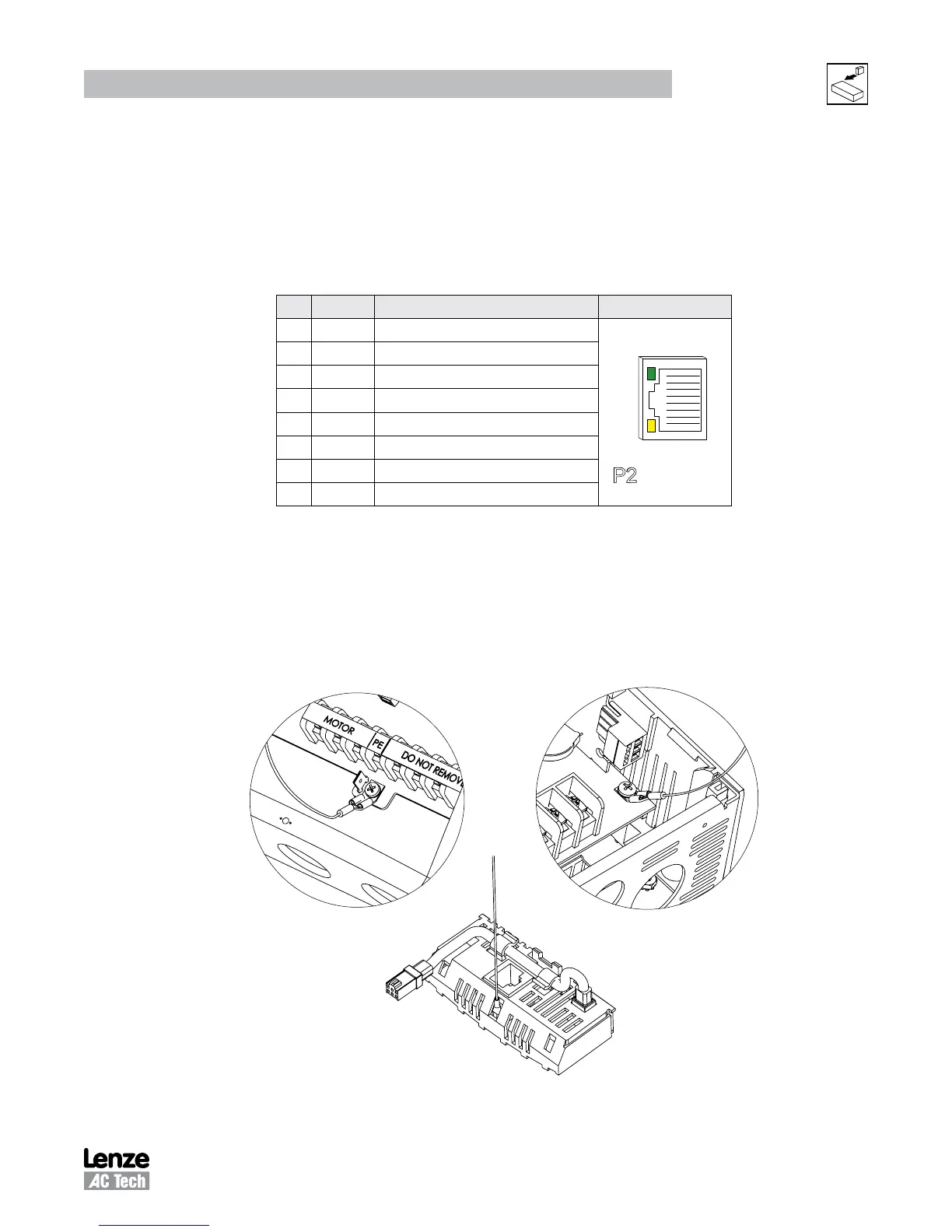
Table 2: P2 Pin Assignments (Communications)
Pin Name Function RJ45 Connector
1 + TX Transmit Port (+) Data Terminal
ETHERNET
1
8
P2
2 - TX Transmit Port (-) Data Terminal
3 + RX Receive Port (+) Data Terminal
4 N.C.
5 N.C.
6 - RX Receive Port (-) Data Terminal
7 N.C.
8 N.C.
The status LEDs integrated in the RJ-45 socket indicate link and activity. The green LED indicates whether
a link is established with another network device. The yellow LED indicates link activity and flashes when
data is received by the EtherNet/IP module.
3.2.2 Grounding
The SMV EtherNet/IP module must be gounded. Attach the ground wire/lug from the module to one of the
the chassis ground screws on the drive as illustrated in Figure 7.
Figure 7: Wiring the EtherNet/IP Module Ground Harness