5
Electrical installation
Control connections
EDK71MMXXX-020 DE/EN/FR 1.0
L
24
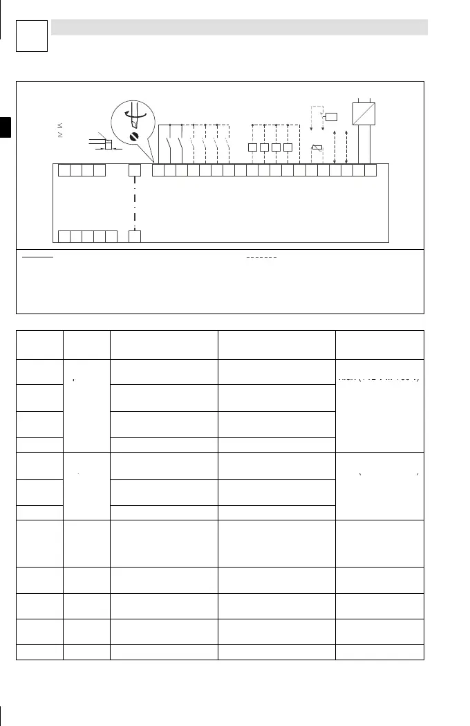
Abb. 1-16
start003
1W 1V
L1 L2
L3
BN PE E1
20
+18...30 VDC
28
E2
E3
E4
E5
A1
7
A2
A3
A4
7
A+ A-
59 7 X3
1U
B1 B2 PE
T1 T2
~
–
Z Z Z Z
starttec
ϑ >
0.5...0.6 Nm
4.4…5.3 lb-in
6mm
1.5 mm
AWG 16
2
Min. wiring required for operation Possible wiring
starttec enable/inhibit
Digital inputs
Digital outputs with load [Z]
Motor temperature monitoring
AS-interface (in preparation)
External voltage supply for controlling the starttec
X3 Signal
type
Function
(bold = Lenze setting)
Level Data
28
Digital
inputs
starttec enable/inhibit HIGH = starttec enabled
LOW = starttec inhibited
LOW (0 V ... +3 V)
HIGH (+12 V ... +30 V)
E1
starttec activation
(freely assignable)
HIGH = starttec active
LOW = starttec not active
Input current: max. 8
mA at 24 V
E3 Brake control
(freely assignable)
HIGH = brake released
LOW = brake activated
E2, E4, E5 freely assignable HIGH / LOW
A1
Digital
outputs
starttec active
(freely assignable)
HIGH = starttec is active
LOW = starttec is not active
LOW (0 V ... +3 V)
HIGH (+12 V ... +30 V)
A3
Brake active
(freely assignable)
HIGH = brake is released
LOW = brake is active
Output current: max.
200 mA per output
A2, A4 freely assignable HIGH / LOW
59 – External DC supply for
controlling the starttec,
reference: X3/7
+18 VDC ... +30 VDC Current consumption:
min. 200 mA
starttec s witches off if
voltage <18 VDC
20 – Internal DC supply,
reference: X3/7
+18 VDC ... +30 VDC Output current: max.
500 mA
A+, A- – AS-interface – only active with
E71MM402FAxxx
T1, T2 – PTC thermistor or
thermostat (NC contact)
– –
7 – GND, reference potential – –