15
ENGLISH
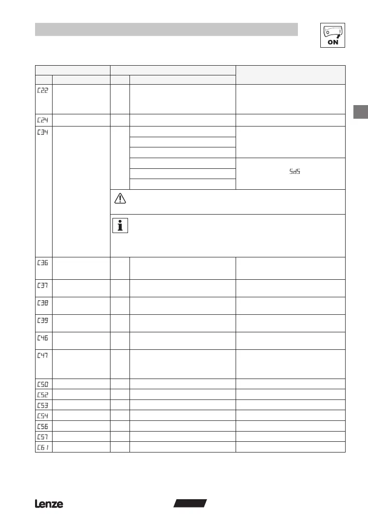
Commissioning
Code Possible Settings
IMPORTANT
No. Name Lenze Selection
Current limit 200 30 {%} 200
Reference: Tmd rated output current
• When the limit value is reached, either the
acceleration time increases or the output
frequency decreases
• When c73 = 0, max setting is 167%
Accel boost 0.0 0.0 {%} 20.0 Accel boost is only active during acceleration
Configuration -
analog input
0 0 0...10 V • Voltage reference applied to 8U
• Tmd does not provide -10 V supply for
C34 = 2
• C34 = 2 disabled in vector torque mode
1 0...5 V
2 -10...+10 V
3 0...20 mA • Current reference applied to 8I
• C34 = 5 will trigger
fault if signal falls
below 2 mA
4 4...20 mA
5 4...20 mA monitored
WARNING!
When running with -10...+10V reference (C34=2), a loss of reference will result in 5%
motor speed (0.05xC11).
Note
When C34 = 2:
• Rotation is determined by the polarity of the -10...+10 V signal:
+0.1...+10 V = CW and -0.1...-10 V = CCW (all other rotation commands are disabled)
• C11 sets maximum frequency in both directions (C10 is not active)
• CE1...CE4 = 6 or 7 will only start the controller, not select rotation
C
Voltage - DC injection
brake (DCB)
4.0 0.0 {%} 50.0 • See CE1...CE4 and c06
• Conrm motor suitability for use with DC
braking
Fixed setpoint 1
(JOG 1)
20.0 0.0 {Hz} 240 Lenze setting: active at E1 = HIGH
Fixed setpoint 2
(JOG 2)
30.0 0.0 {Hz} 240 Lenze setting: active at E2 = HIGH
Fixed setpoint 3
(JOG 3)
40.0 0.0 {Hz} 240 Lenze setting: active at E1 = HIGH and E2
= HIGH
Frequency setpoint 0.0 {Hz} 240 Display: Setpoint via analog input, function
UP/DOWN, or LECOM
Torque setpoint/range 100 0 {%} 400 • When C14 = 5 and C01 = 1, 5, 7, 9, 11,
sets the torque setpoint
• When C14 = 5 and C01 = 0, 2, 4, 6, 8, 10,
sets the torque range for C34
C
Output frequency 0.0 {Hz} 240 Display
Motor voltage 0 {V} 999 Display
DC bus voltage 0 {V} 999 Display
Motor current 0.0 {A} 400 Display
Controller load 0 {%} 255 Display
C
Motor torque 0 {%} 400 Display: vector mode only (C14 = 4, 5)
Heatsink temp 0 {C} 255 Display