17
ENGLISH
Commissioning
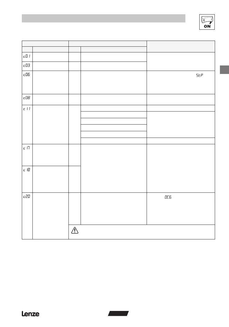
Code Possible Settings
IMPORTANT
No. Name Lenze Selection
Acceleration time 2 5.0 0.0 {s} 999 • Activated using CE1...CE4
• c01 = frequency change 0 Hz...C11
• c03 = frequency change C11...0 Hz
• For S-ramp accel/decel, adjust c82
Deceleration time 2 5.0 0.0 {s} 999
Holding time -
automatic DC injection
brake (Auto-DCB)
0.0 0.0 {s} 999
0.0 = not active
999 = continuous brake
• Automatic motor braking after by
means of motor DC current for the entire
holding time (afterwards: U, V, W inhibited)
• Conrm motor suitability for use with DC
braking
Analog output scaling 100 0.0 999 When 10 VDC is output at terminal 62, it will
equal this value (see c11)
Configuration -
Analog output (62)
0 0 None
1 Output frequency 0-10 VDC Use c08 to scale signal
Example: c11 = 1 and c08 = 100:
At 50 Hz, terminal 62 = 5 VDC
At 100 Hz, terminal 62 = 10 VDC
2 Output frequency 2-10 VDC
3 Load 0-10 VDC
4 Load 2-10 VDC
5 Dynamic braking Only used with DB option
Configuration - Digital
output (A1)
0 Output is energized if
0 Ready
1 Fault
2 Motor is running
3 Motor is running - CW rotation
4 Motor is running - CCW rotation
5 Output frequency = 0 Hz
6 Frequency setpoint reached
7 Frequency threshold (C17) exceeded
8 Current limit (motor or generator
mode) reached
Configuration - Digital
output (A2)
1
I2t switch-off (thermal
motor monitoring)
100 30 {%} 100
100% = Tmd rated output current
• Triggers
fault when motor current
exceeds c20 for too long
• Correct setting = (motor nameplate current)
/ (Tmd output current rating) X 100%
• Example: motor = 6.4 amps and
Tmd = 7.0 amps; correct setting = 91%
(6.4 / 7.0 = 0.91 x 100% = 91%)
WARNING!
Maximum setting is rated motor current (see nameplate). Does not provide full motor
protection!