Fast commissioning steps at a glance
Leuze electronic BPS 34 11
TNT 35/7-24V
Connecting the PROFIBUS
The PROFIBUS is connected via DP IN or, in the case of a continuing network, via DP OUT.
If DP OUT is not used, the PROFIBUS must be terminated at this point with an M12 termi-
nator plug (see chapter 10.4 "Accessories - Termination").
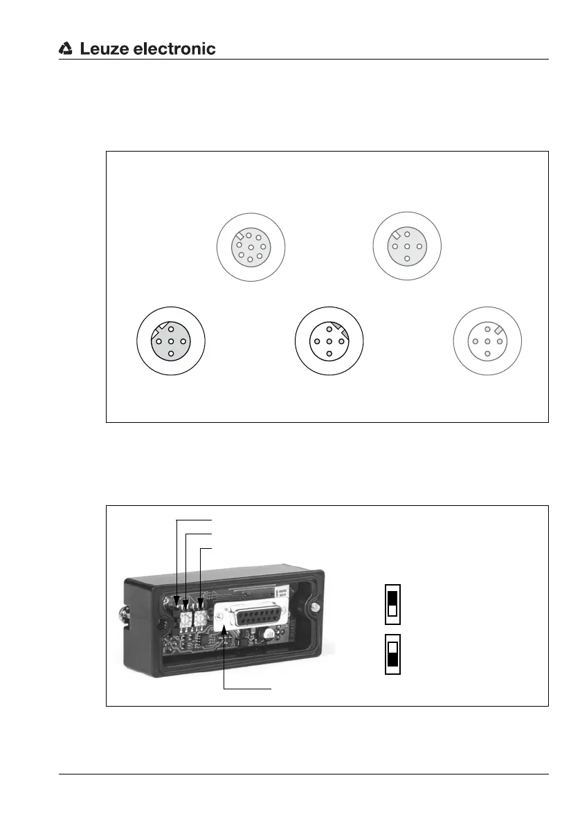
Figure 3.3:BPS 34 with MS 34 103/MS 34 105 – DP IN and DP OUT connections
Setting the PROFIBUS address
The PROFIBUS address must be set in the MS 34 10x connector plug hood. The correct
address setting on the PROFIBUS network is indicated by the green LED on the MS 34 10x.
Figure 3.4:View of the inside of the MS 34
Socket
(A-coded)
Socket
(A-coded)
Socket
(B-coded)
Plug
(B-coded)
Plug
(A-coded)
DP IN
GND
3
2
1
4
PE
A (N)
B (P)
VCC
DP OUT
VCC
1
2
3
4
A (N)
B (P)
GND
PE
PWR IN
SWIN
SWOUT
3
2
1
4
GND VIN
PE
SW IN/OUT
1
2
3
4
VOUT
PE
SWIN
SWOUT
GND
1
2
3
4
MSD
5
6
7
/SERV
VIN
TXD
RXD
SCL
SDA
GND
/INT
Slide switch for the hundreds (marked with 10
2
)
Rotary switch for the tens (marked with 10
1
)
Rotary switch for the single digits (marked with 10
0
)
Connection plug to the BPS 34
Position of the slide
switches:
Top address
100 - 126
Bottom address
1 - 99