Fast commissioning steps at a glance
12 BPS 34 Leuze electronic
PROFIBUS manager
Install the GSD file associated with the BPS 34… in the PROFIBUS manager of your control.
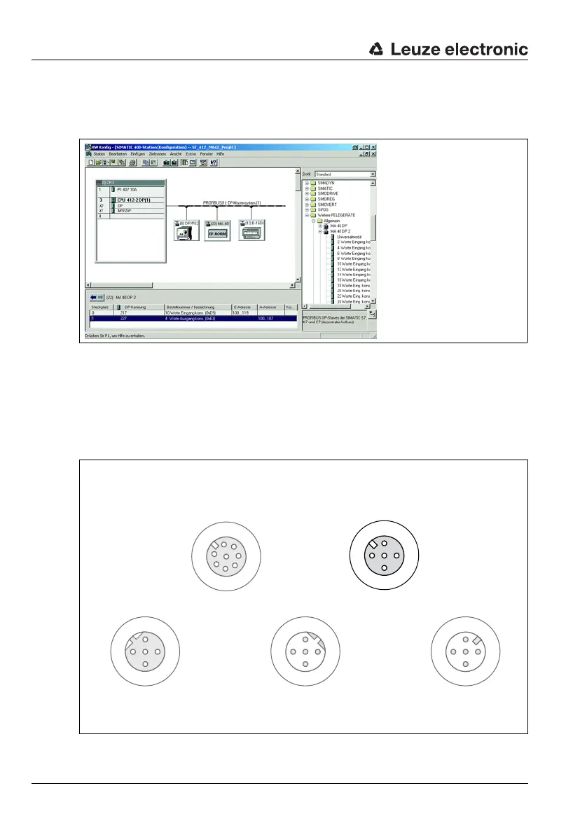
Activate the desired modules (at least module 1 - position value).
Figure 3.5:Example PROFIBUS manager
Store the slave address for the BPS 34 in the PROFIBUS manager. Ensure that the address
is the same as the address configured in the device.
Connecting the switching input/switching output to the BPS 34
The switching input/switching output is connected via SW IN/OUT.
Figure 3.6:BPS 34 with MS 34 103/MS 34 105 – SW IN/OUT connection
Socket
(A-coded)
Socket
(A-coded)
Socket
(B-coded)
Plug
(B-coded)
Plug
(A-coded)
SW IN/OUT
1
2
3
4
VOUT
PE
SWIN
SWOUT
GND
PWR IN
SWIN
SWOUT
3
2
1
4
GND VIN
PE
DP IN
GND
3
2
1
4
PE
A (N)
B (P)
VCC
DP OUT
VCC
1
2
3
4
A (N)
B (P)
GND
PE
1
2
3
4
MSD
5
6
7
/SERV
VIN
TXD
RXD
SCL
SDA
GND
/INT