Device parameters and interfaces
Leuze electronic BPS 34 65
TNT 35/7-24V
Input data
Note!
These input data signal the state of the BPS 34:
•Init: Base setting during initial startup of the BPS 34
• Idle: The BPS 34 is in idle state (scanning beam is off, but motor is running)
• Measure: The BPS 34 is in measurement state (data are output in module 1)
• Standby: The BPS 34 is in waiting state (laser off and motor off).
Output data
Internal address
of module 9
Measurement start mode
address 0
Measurement stop mode
address 1
Stop timeout
address 2
03 01 04 27 10
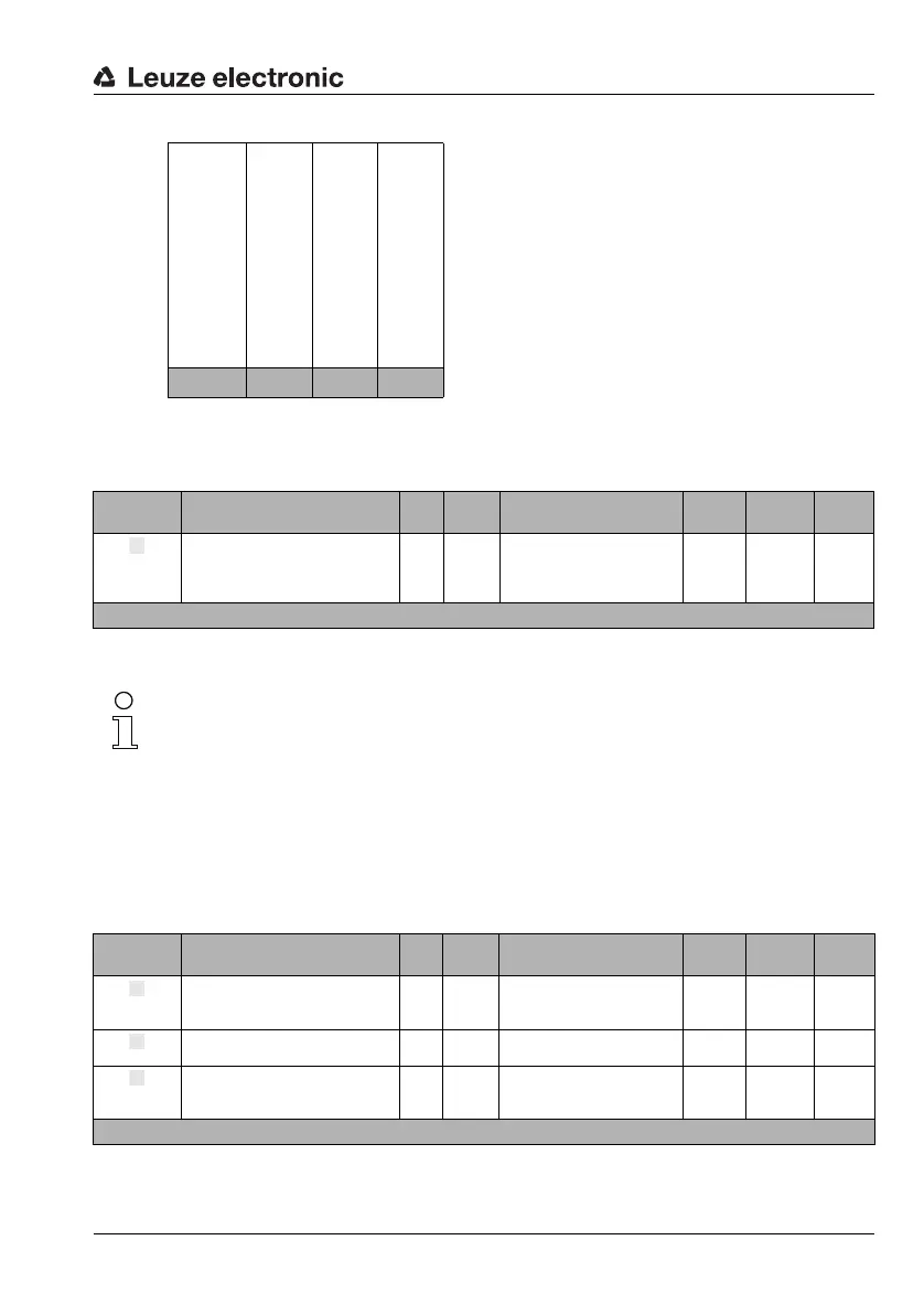
Input data Description Rel.
addr.
Data
type
Value range Default Unit CR to
module
Position
control
state
Signals the current state of the
internal position control of the
BPS 34
0
unsign
8
0: Init
1: Idle
2: Measure
4: Standby
0 ––
Input data length: 1 byte
Output
data
Description Rel.
addr.
Data
type
Value range Default Unit CR to
module
Start
event
Event starts position measure-
ment
0.0 Bit 0 -> 1: Start 0 –7g
Stop event
Event stops position measure-
ment
0.1 Bit 0 -> 1: Stop 0 ––
BPS
standby
Switches the BPS 34 to standby
operation
0.7 Bit
0: BPS active
1: BPS in standby mode
0 ––
Output data length: 1 byte