Display elements
18 SOLID-2 Leuze electronic
Review-Stand, , 8. April 2015
DEUTSCH ENGLISH FRANÇAIS ITALIANO ESPAÑOL NEDERLANDS
4.2 Receiver status displays
LED1 and the 7-segment display report on the operating states of the Receiver Standard.
LED2 is added in case of Receiver Extended.
4.2.1 7-segment display
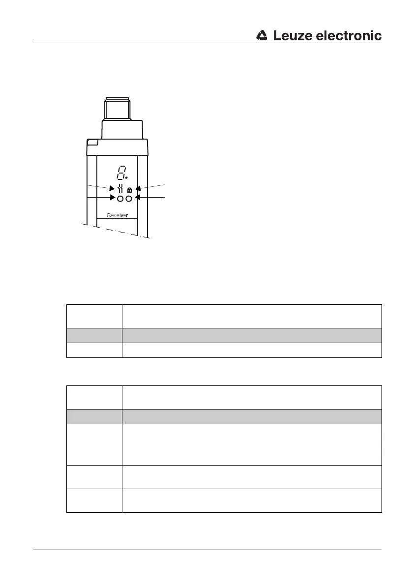
After the electrical supply voltage is turned on, the following data appear on the receiver’s
7- segment display:
a=Symbol for OSSDs
b=LED1 = red/green
c=Symbol for interlocking state
d=LED2 = yellow
Fig. 4.2-1: Receiver, status displays
7-segment
display
Meaning
Permanent display after startup
1 or 2 Indication of transmission channel TC1 or TC2
Table 4.2-1: Receiver, 7-segment permanent displays
7-segment
display
Meaning
Temporary event displays, 1 s per display
E xx Locking status display “error“, which can be eliminated by the user
E xx = Error code (for example contactor monitoring error E 30, see Chap-
ter 9). The display shows repeating the sequence of E, 3 (1st position)
and 0 (2nd position).
F xx Locking status display „device fault“ and an internal fault code.
Receiver must be replaced.
1 or 2
flashing
Flashing transmission channel number → weak signal display, device not
adjusted optimally or contaminated front screens
Table 4.2-2: Receiver, 7-segment temporary event display