Electrical connection
Leuze electronic SOLID-2 35
TNT 35/7-24V
Review-Stand, , 8. April 2015
DEUTSCHENGLISHFRANÇAISITALIANOESPAÑOLNEDERLANDS
6.1.3 Receiver Extended
6.1.3.1 Selection of the transmission channel
The polarity of of the power supply at pin2 and pin7 determines the selected optical
transmission channel:
If +24V DC is present on pin2 and 0V on pin7 transmission channel 1 is selected.
If 0V is present on pin2 and +24V DC on pin7 transmission channel 2 is selected.
Note:
Make certain to select the same transmission channel for both, for transmitter and receiver.
For optimal shielding cables must be used, where the shield is led on the knurled nut of
the connecting cable socket (such cables are listed under accessories in Chapter
11.3).
6.1.3.2 Operating mode selection RES and contactor monitoring (EDM)
The Receiver Extended has to be connected via the 8-pin M12 connector. The operating
modes S/R and EDM can be activated in several combinations using the pins BA1 (pin1)
and BA2 (pin3) .
1 = white
2 = brown
3 = green
4 = yellow
5=grey
6=pink
7=blue
8 = black
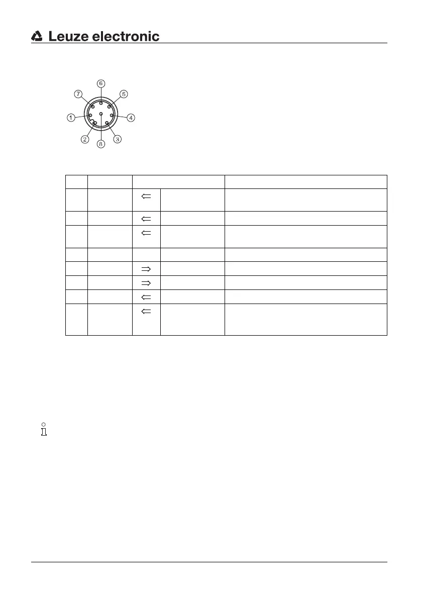
Fig. 6.1-5: SD2R 8-pin (view of the pins)
Pin Color Assignment Inputs/outputs
1 white Operating
mode selection
Input BA1
2 brown Supply voltage +24V DC for TC1 or 0V for TC2
3 green Operating
mode selection
Input BA2
4 yellow nc
5 grey Output OSSD1, switching semicontactor output
6 pink Output OSSD2, switching semicontactor output
7 blue Supply voltage 0V for TC1 or +24V DC for TC2
8 black/
connector
enclosure
Shield Functional earth
Table 6.1-3: Receiver Extended, connection assignment