Electrical connection
Leuze electronic SOLID-2 33
TNT 35/7-24V
Review-Stand, , 8. April 2015
DEUTSCHENGLISHFRANÇAISITALIANOESPAÑOLNEDERLANDS
6.1.2 Receiver Standard
Warning!
The Receiver Standard does not offer the functions start/restart interlock and EDM. These
functions have to be carried out by the downstream machine control unit if required by the
safety category.
Note:
For optional shielding cables must be used, where the shield is led on the knurled nut of the
connecting cable socket (such cables are listed under assessories in Chapter 11.3).
The polarity of of the power supply at Pin1 and Pin3 determines the selected optical
transmission channel. If +24V DC is present on Pin1 and 0V on Pin3 transmission channel
1 is selected. If 0V is present on Pin1 and +24V DC on Pin3 transmission channel 2 is
selected.
Note:
Make certain to select the same transmission channel for both, for receiver and transmitter.
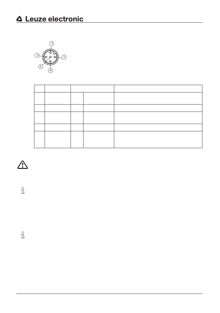
1 = brown
2 = white
3 = blue
4 = black
5=grey
Fig. 6.1-3: SD2R 5-pin (view of the pins)
Pin Color Assignment Inputs/outputs
1 brown ⇐ Supply volta-
ge
+24V DC for TC1 or 0V for TC2
2 white Output OSSD2, switching semicontactor output
3 blue ⇐ Supply volta-
ge
0V for TC1 or +24V DC for TC2
4 black Output OSSD1, switching semicontactor output
5 grey/
connector
enclosure
⇐ Shield Functional earth
Table 6.1-2: Receiver Standard, connection assignment