Electrical connection
Leuze electronic SOLID-2 31
TNT 35/7-24V
Review-Stand, , 8. April 2015
DEUTSCHENGLISHFRANÇAISITALIANOESPAÑOLNEDERLANDS
6 Electrical connection
• The electrical connection must be performed by experienced personnel. Knowledge of
all safety instructions in these connecting and operating instructions is part of this
competence.
• The external supply voltage of 24V DC ± 20 % must guarantee safe isolation from mains
voltage and be able to bridge a power outage period of at least 20 ms. Leuze
electronic offers suitable power supplies (see list of accessories in the Appendix).
• The power supply selected must not support any other parts of the machine with power
other than the safety components connected. It must provide at least 1 A. Transmitter
and receiver must be fused against overcurrent.
• It is vital during the electrical installation for the power of the machine or system to be
protected is switched off and locked, so that the dangerous movements cannot be
started unintentionally. Only after the safety function on the protective device is entirely
checked, its connection to the machine is permissible. For more details see
Chapter 8
and 11.4.
6.1 M12 connection
Transmitter and Receiver Standard are equipped with M12, 5-pin plugs while the Receiver
Extended providing additional functions is equipped with a M12, 8-pin plug.
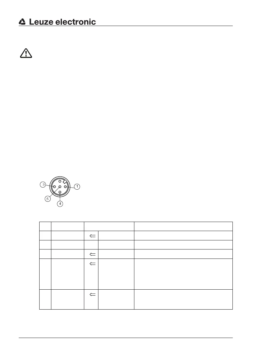
6.1.1 Transmitter
1 = brown
3 = blue
4 = black
5=grey
Fig. 6.1-1: SD2T 5-pin (view of the pins)
Pin Color Assignment Inputs/outputs
1 brown Supply voltage +24V DC for TC1 or 0V for TC2
2 white nc.
3 blue Supply voltage 0V for TC1 or +24V DC for TC2
4 black Test in Test input
Connected to +24V DC
→ internal test activated
Connected to 0V or disconnected
→ external test activated
5 grey/
connector
enclosure
Shield Functional earth
Table 6.1-1: Transmitter, connection assignment