Electrical connection
36 SOLID-2 Leuze electronic
Review-Stand, , 8. April 2015
DEUTSCH ENGLISH FRANÇAIS ITALIANO ESPAÑOL NEDERLANDS
Warning!
The adaptation of the operating mode is only be carried out in the switched off state of the
receiver. If the adaptation is made during operation, the new values will not be accepted
until the power supply was switched off.
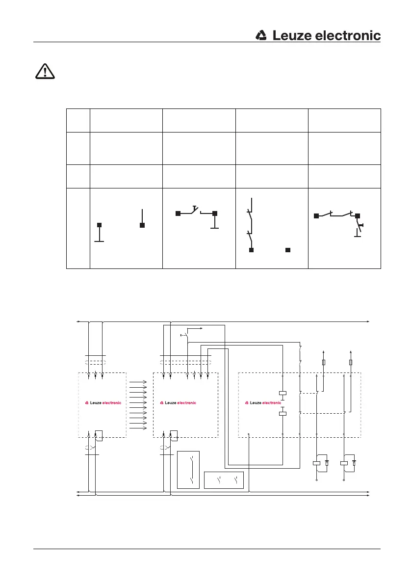
6.1.3.3 Connection example
Without RES Wit-
hout EDM
With RES
Without EDM
Without RES
With EDM
With RES
With EDM
BA1
pin1
0V Start/restart button
to BA2
EDM feedback
loop k1/k2 at
+24V
DC
EDM feedback
loop k1/k2 at BA2
BA2
pin3
+24V DC 0V n.c. Via start/restart
button to 0V
Connection
Table 6.1-4: Receiver Extended, operating mode selection
Fig. 6.1-6: Connection example SOLID-2E with MSI-RM2 Safety Relay
OSSD2
0V
FE
FE
0V BA1
SOLID-2 E / SD2R E
+24V
Te st
n.c.
+24V
SOLID-2 E / SD2T MSI-RM2
n.c.
OSSD1
BA2
Var. B
Var. A
A1
A2
-K3
65
1
2
1
2
3SH
8
-W1
7SH
-W2
-S1
A2
5
14B3
6
Y1
1
B1
4
-A3
11
3
12 22
2
-K4
-K3
A1
A2
-K4
21Y2
-W1
41
5
-W2
7
21
-A2
4
3
24
1
-A1
3
2
-K3 -K4-K4
-K3
0V
PE
+24V.
0V
+24V
PE
0V
L+L+
L- L-