1-9
Getting Started
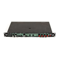
PCM 81
INSTALLATION NOTES
MOUNTING
The PCM 81 uses one EIA-standard rack space, and can be
mounted on any level surface or in a standard 19 inch (483 mm)
rack. If the PCM 81 is mounted in a rack or road case, support the
rear of the chassis to prevent possible damage from mechanical
shock and vibration.
The maximum ambient operating temperature is 104°F (40°C).
Provide adequate ventilation if the PCM 81 is mounted in a closed
rack with heat-producing equipment such as power amplifiers.
POWER REQUIREMENTS
The PCM 81 is equipped with a 3-pin IEC power connector and
detachable cord.
The PCM 81 will operate with power sources from 100 to 240 volts
AC, 50-60Hz. Power switching to actual line voltage is automatic.
AUDIO CONNECTIONS
Analog Audio
For best performance, maintain balanced connections, and use
high-quality, low-capacitance, twisted-shielded pair cable.
When connecting to single-ended, unbalanced devices, connect
the low side to signal ground at the unbalanced piece of
equipment. Output level does not change when connected to an
unbalanced input.
Mono Applications
Use a Y-connector inserted at the analog inputs and outputs to
have the signal summed to mono.
Note:
Be careful to keep input and output to all channels
wired consistently. Out-of-phase wiring can produce
audible effects.
Digital Audio
S/PDIF (CP-340 Type II) Consumer Digital Audio connections
require 75Ω coaxial cable suited for digital audio or video signals.
Audio grade cable is not suitable.
AES/EBU connections require balanced connections using
high-quality, low-capacitance, controlled-impedance, data
communication, twisted-shielded pair cable. Microphone cable
may introduce a significant amount of jitter into the signal, causing
distortion.
CONTROL CONNECTIONS
Footswitch/Foot Controller
One 1/4 inch T/R/S phone jack is provided for 2 momentary
footswitches. Another 1/4 inch T/R/S phone jack is provided for a
footpedal (minimum 100Ω to maximum 10k impedance).
Normally open or normally closed momentary switches are
suitable. At power on, the PCM 81 assumes the switch is off. Use
shielded, twisted-pair cable with shield connected to sleeve. See
diagram on page 1-9.

 Loading...