will protect the pump in the event of operation under sustained high load or
under fault conditions.
The controller pr
ovides the user interface. The pump may be operated in
these modes:
▪ Manually, using the buttons on the interface panel. Refer to (
▪
‑ and )
▪ Remotely via the 15-pin D-Sub digital I/O connector.▪
Logic interface
The pump contr
oller can be operated via the 15-pin D-sub digital I/O
connector. The signals on the logic interface are of the following types:
▪ Control inputs: there are switch-type signals that are used to control the▪
pump
▪ Status outputs: these outputs identify the status of the system.▪
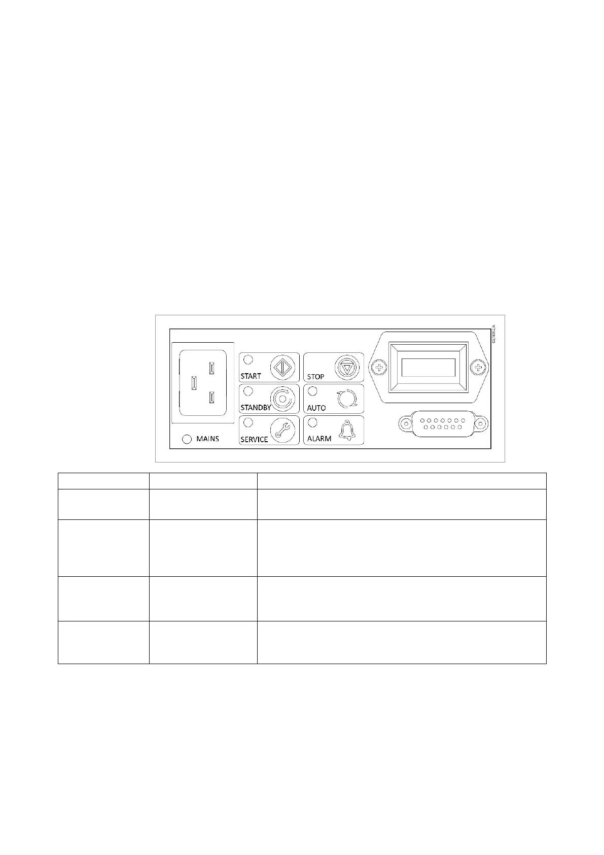
Figure 2. 1-Phase pump user interface panel
Operation Select Status
Apply power MAINS POWER
The pump will remain stopped (factory default).
The POWER INDICATOR will illuminate.
Start the pump START BUTTON
The pump will accelerate up to full running speed.
The RUN INDICATOR will ash while accelerating.
The RUN INDICATOR will remain ON when the pump reaches
full speed.
Stop the pump STOP BUTTON
The pump will decelerate and stop running.
The RUN INDICATOR will ash while decelerating.
The RUN INDICATOR will go OFF when the pump has stopped.
Select and dese
lect
the standby speed
STANDBY MODE
SELECT BUTTON
When engaged, the STANDBY INDICATOR will illuminate and
the pump will run at the standby speed setting of 75% of full
speed.
16 300668736_002_C7 - © Leybold
Description