Select and dese
lect
the Auto-run func
tion
START or STOP
BUTTON
(>8 seconds)
When engaged, the AUTO‑RUN INDICATOR will illuminate. The
pump will restart automatically after the power has been r
e
stored.
To reset the
service
indicator
SERVICE RESET
BUTTON
To reset the service indicator, press and hold the service reset
button for more than 5 seconds.
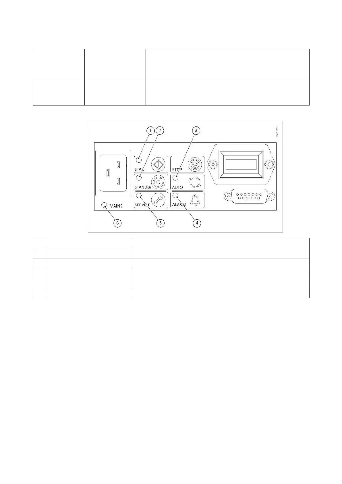
Figure 3. 1-Phase pump LED indicators
1 Run indicator Indicates that the pump is operating
2 Standby mode indicator Indicates that the standby mode has been selected
3 Auto-run indicator Indicates that the auto run mode has been selected
4 Alarm indicator Indicates an alarm has been triggered
5 Service indicator Indicates that a service interval has been reached
6 Power indicator Indicates that electrical mains supply to the pump is ON
3.33-phase pump
The 3-phase dir
ect-on-line pump includes a customer interface, electric
terminal box and an embedded 3-phase electric motor. The electric terminal
box provides a method for connecting and conguring the 3-phase supply
to the embedded 3-phase motor. The electric terminal box also provides the
user interface, comprising of:
▪ 3-Phase power input eld wiring terminals and cable gland▪
▪ Hours counter (This contains a compact lithium cell battery which▪
contains 1,2 DimethoxyEthane, included in the REACH candidate list
of substances of very high concern, in the electrolyte.)
3.4Gas ballast control
To pump high vapour loads, gas ballast can be delivered into the pump to
prevent condensation of the vapour carried by the pumped gases.
Air can be introduced to the low vacuum stages through the gas
ballast control refer to
.
Alternatively, an inert gas such as nitrogen can be supplied through a
300668736_002_C7 - © Leybold 17
Description