Pin
number
Signal Use
10 Chassis/Screen Screen
11 Not connected Unused control pin
12 Chassis/Screen Screen
13 Not connected Unused control pin
14 REMOTE-Control Input
Connect to pin 2 (0 V) to enable remote control via Parallel
control mode
15 NORMAL-Status Output
Logic LOW when the pump r
otational speed is at normal speed
or above.
7.3.3Remote control and monitoring
Note:
Connect the control equipment to the control input pins of the logic interface
mating half. The control inputs are as follows:
▪ Start▪
▪ Standby speed▪
To activate any of these control inputs, connect the relevant control input
(pin 14) to the (0 V) control reference.
To monitor the normal status output, connect the control equipment to the
Normal status output (pin15) and to (pin2) of the logic interface mating half.
The output can be used to control other devices in the pumping system.
The output can drive a low power relay of up to 24V coil rating (up to
10mA).
To monitor the fail status output, connect the control equipment to the fail
output (pin 7) and to (pin 2) of the logic interface mating half. The output
can be used to control other devices in the pumping system. The output can
drive a low power relay of up to 24 V coil rating (up to 10 mA).
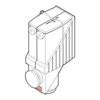
7.4Manual operation 3-phase pump
CAUTION: PUMP DAMAGE
Do not run the pump at frequencies above 65 Hz as this could cause damage to
the pump.
The 3-phase pump is a direct-on-line pump application with no speed
control. The pump running speed is determined by the electrical frequency
of the customer’s supply, i.e. 50 Hz or 60 Hz. Refer to
.
The pump will start as soon as power is applied.
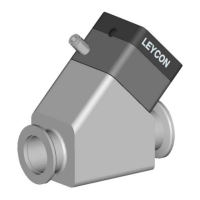
7.5Use of a gas ballast control 1 and 3-phase pump
The gas ballast control can be used to optimise the performance of the
pump for the application. The position of the gas ballast control can be
changed when the pump is either off or operating.
40 300668736_002_C7 - © Leybold
Operation