Table 12. FAIL status output
Type Open collector transistor plus pull up resistor.
Fail OFF (4.7 k pull up + diode to 12 V d.c.)
OK ON (< 0.8 V d.c. sinking 10 mA)
Maximum current rating 10 mA
Maximum voltage rating 28.8 V d.c
7.3.2Digital I/O interface connector pins
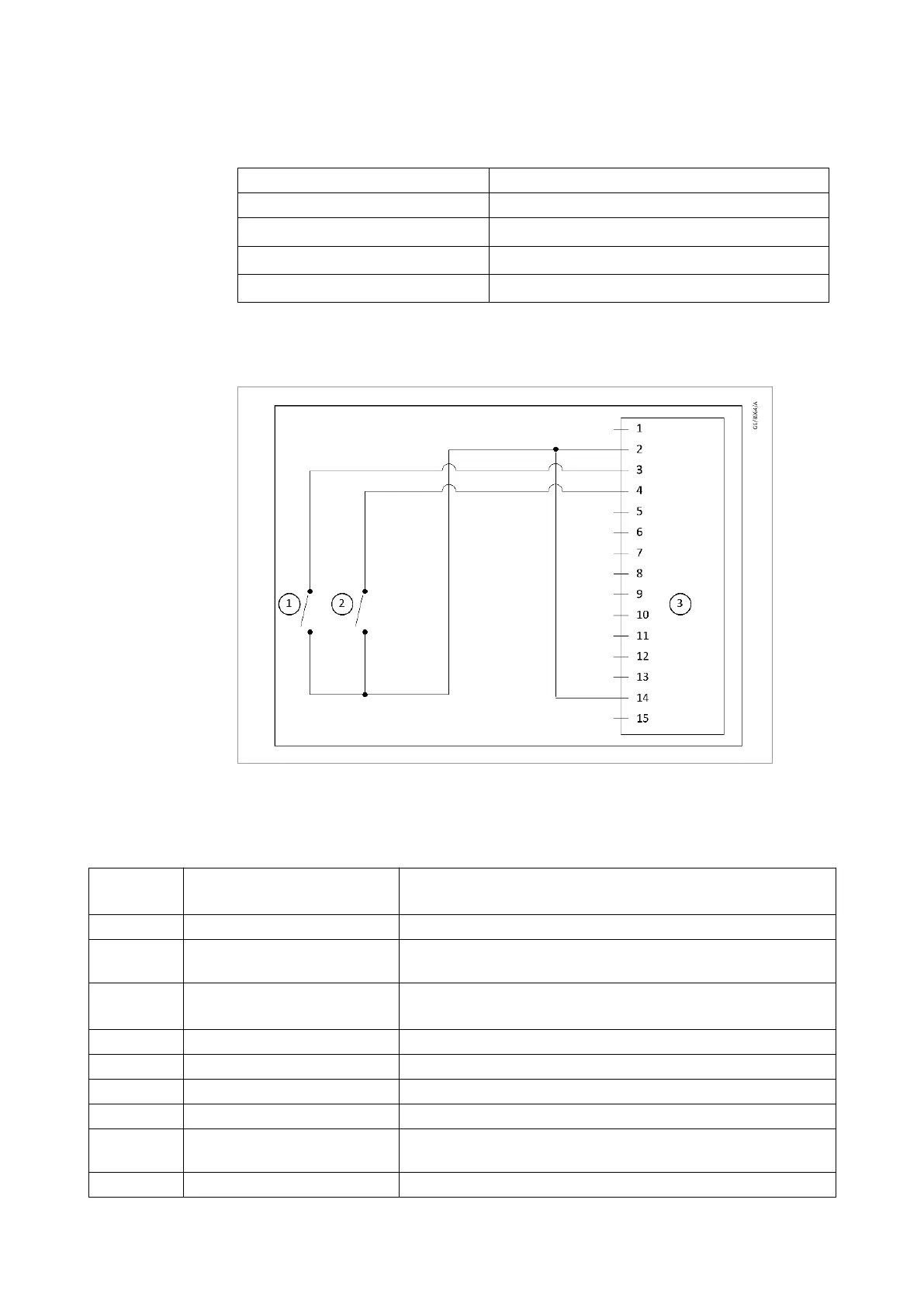
Figure 14. Logic interfcae connections-parallel control
Table 13 Digital I/O interface connector pins
Pin
number
Signal Use
1 Not connected Unused control pin
2 0 V Control reference
(0 V) reference for ALL control and status signals listed within
this table.
3
START/STOP
control input
Connect to pin 2 (0 V) to START the pump system.
4 STANDBY-Control Input Connect to pin 4 (0 V) to enable STANDBY
5 Not connected Unused control pin
6 Not connected Unused control pin
7 FAIL-Status Output Logic HIGH when a fail/fault condition exists
8 (0 V) Control reference
(0 V) reference for ALL control and status signals listed within
this table.
9 Not connected Unused control pin
300668736_002_C7 - © Leybold 39
Operation