If inverter technology is required; suitable in-line ltering between the inverter
and the pump system must be applied. The ltering must reduce the total
harmonic distortion of the supply voltage to less than 5%. Please consult the
inverter manufactur
er for more details on the type of lter required.
In addition to the in-line ltering, the correct fuse protection is still required.
Refer to tables in
on page 30.
Make sure the access to the pump electrical supply cable is not obstructed
when locating the pump.
If using an earth leakage current device, for example a Residual Current
Device (RCD), use a 30 mA (minimum) rated unit to avoid nuisance tripping
during start up.
Note:
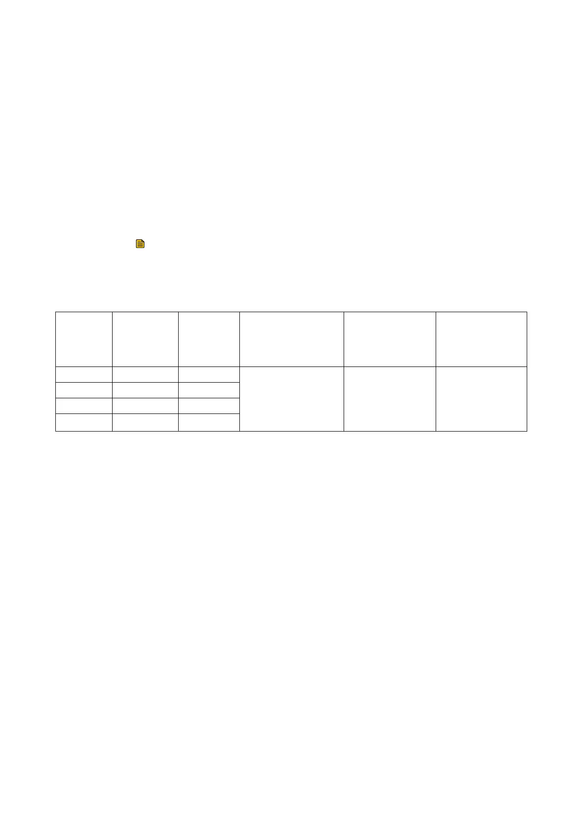
Table 8 Input supply
Voltage
(a.c. rms)
Frequency
(Hz)
Rated sys‐
tem input
curr
ent
(A rms)
Minimum wire gauge
(4 wire: 3-phase+PE)
Recommended
wire
temperature
Recommended UL
style number
200 50 2.5
16 AWG/1.5 mm
2
105 °C UL1015
200-208 60 2.5
380-415 50 1.25
460
60 1.25
The recommended overall cable gauge, including 3 live wires and a PE wire
with the individual wire specication dened in the table, is approximately
9.6 mm outer diameter. The M20 cable gland on the front panel of the pump
is suitable for a cable diameter range: 5‑12 mm.
Use the following procedure to connect a mains cable to the 3-phase pump:
32 300668736_002_C7 - © Leybold
Installation