Installation
37
300554859_002_C0 - 11/2016 - © Leybold
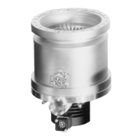
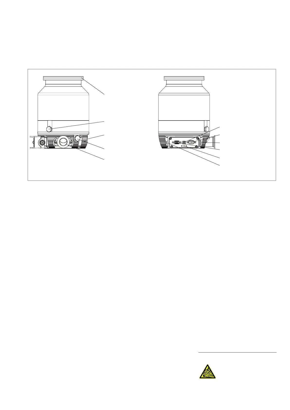
Fig. 3.11 Connections at the TURBOVAC 350/450 i
High-vacuum flange
Venting connection
G1/8“
Mounting surface for
water cooling
Purge gas connection
G1/8“
Forevacuum connection
(is connected)
USB interface X106
RS 485 interface X104
DC input DC IN X10
REMOTE interface X1
LEDs
Accessory connection
DC OUT (M8) X201
3.8 Connect a Power Failure Venting Valve or a Venting Valve
The power failure venting valve (normally open) or venting valve (normally
closed, vents at stop command) vents the pump and the forevacuum line
when the pump is switched off and thus keeps oil vapor from diffusing back
from the forevacuum line. A choke nozzle in the vent port ensures that the
pump is not vented too fast.
The max. permissible pressure in the pump must not exceed 1.4 bar (abs.).
Unscrew and remove the locking screw and the gasket from the venting con-
nection of the TURBOVAC.
Screw in the venting valve and the gasket into the vent connection, then plug
in the corresponding control cable into the X203 accessories connection on
the TURBOLAB. The accessory connection is pre-configured for the vent
valve operation. The vent valve will be triggered depending on the frequency
of the TURBOVAC by default. If you have connected are power failure vent-
ing valve (normally open) you must change the operation output of X203;
Menu → Accessory → Vent → change the operation to Power failure vent
(via the TPU interface); If the pump station losses power then the vent valve
will open.
For an overview of the connections, see fig. 3.14 and 3.15.
If applicable connect the venting gas supply at the valve’s inlet (G1/8“).
To change the venting valve function code go to Menu → Accessory → Vent
(via the TPU interface).
The pressure in the pump must not exceed atmospheric pressure.
Observe Safety Information 0.1.2 to 0.1.5.
WARNING
Artisan Technology Group - Quality Instrumentation ... Guaranteed | (888) 88-SOURCE | www.artisantg.com
 Loading...