112 |$33/,&$7,21*8,'(/,1(6
MULTI V IV Outdoor Unit Engineering Manual
'XHWRRXUSROLF\RIFRQWLQXRXVSURGXFWLQQRYDWLRQVRPHVSHFL¿FDWLRQVPD\FKDQJHZLWKRXWQRWL¿FDWLRQ
©
/*(OHFWURQLFV86$,QF(QJOHZRRG&OLIIV1-$OOULJKWVUHVHUYHG³/*´LVDUHJLVWHUHGWUDGHPDUNRI/*&RUS
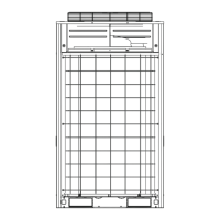
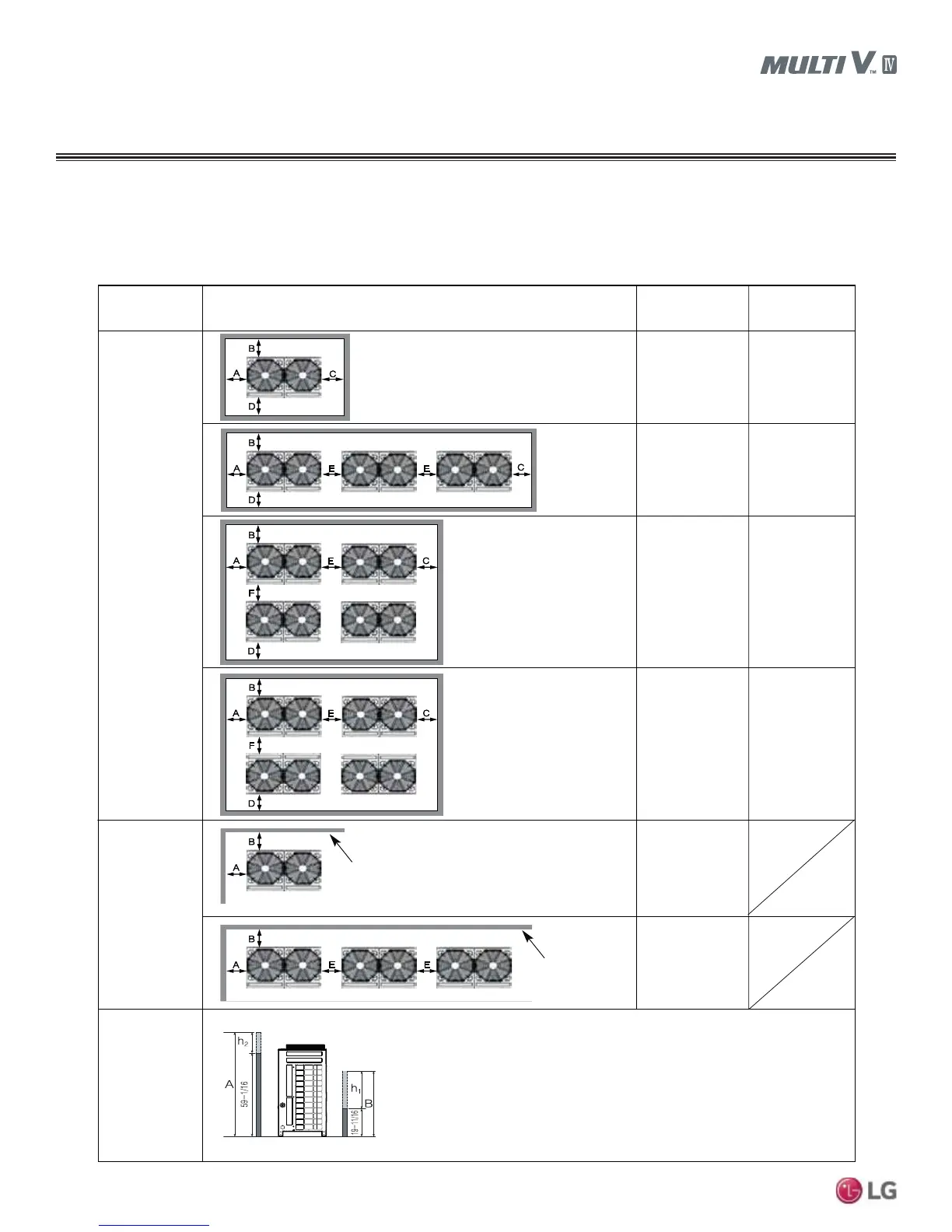
Installation Space
Proper airflow through the outdoor unit coil is critical for proper unit operation. When installing the outdoor unit, consider service, inlet, and
outlet, and minimum allowable space requirements as illustrated in the diagrams below.
Figure 12: Minimum Space Requirements.
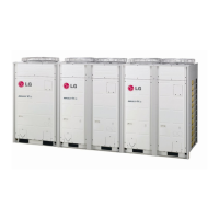
Outdoor Units
PLACEMENT CONSIDERATIONS
Description
Example No.1
7/16” ≤ Space A, C ≤ 1-7/8”
Example No. 2
Space A, C
≥
1-7/8”
Installation Area
Unit(s) is (are)
enclosed by
(4) walls
Two (2) sides
are walls
Wall height
limitations (when
the unit[s] is [are]
surrounded by
four [4] walls)
Front
Front
Front
Front
Front
Front
Front
Front
Front
No limitations on wall height
No limitations on
wall height
Front
• Wall height at the front of the unit must be ≤ 59-1/16 inches.
• Wall height at the inlet side of the unit must be ≤ 19-11/16 inches.
• There are no height limitations for the walls at the sides of the unit.
• If the wall height at the front and inlet sides of the unit are higher than allowable limits,
additional space muct be included.
- Additional Space on the inlet side by 1/2 of h1.
- Additional Space on the front side by 1/2 of h2
- h2 = A(Actual height) - 59-1/16 inches
- h1 = B(Actual height) - 19-11/16 inches
A≥ 7/16” A ≥ 2”
B ≥ 11-13/16” B ≥ 3-15/16”
C ≥ 7/16” C ≥ 2”
D≥ 20” D ≥ 20”
A≥ 7/16” A ≥ 2”
B ≥ 11-13/16” B ≥ 3-15/16”
C ≥ 7/16” C ≥ 2”
D≥ 36” D ≥ 36”
E ≥ 2-3/4” E ≥ 3-15/16”
A≥ 7/16” A ≥ 2”
B ≥ 11-13/16” B ≥ 3-15/16”
C ≥ 7/16” C ≥ 2”
D≥ 36” D ≥ 36”
E ≥ 2-3/4” E ≥ 3-15/16”
F ≥ 24” F ≥ 20”
A≥ 7/16” A ≥ 2”
B ≥ 11-13/16” B ≥ 3-15/16”
C ≥ 7/16” C ≥ 2”
D≥ 36” D ≥ 36”
E ≥ 2-3/4” E ≥ 3-15/16”
F
≥ 36” F ≥ 36”
A≥ 7/16”
B ≥ 11-13/16”
A≥ 200(7-7/8”)
B ≥ 300(11-13/16”)
E ≥ 400(15-3/4”)
G
≥
20” G
≥ 20”