'XHWRRXUSROLF\RIFRQWLQXRXVSURGXFWLQQRYDWLRQVRPHVSHFL¿FDWLRQVPD\FKDQJHZLWKRXWQRWL¿FDWLRQ
©
/*(OHFWURQLFV86$,QF(QJOHZRRG&OLIIV1-$OOULJKWVUHVHUYHG³/*´LVDUHJLVWHUHGWUDGHPDUNRI/*&RUS
132 |5()5,*(5$17'(6,*1
MULTI V IV Outdoor Unit Engineering Manual
/*(QJLQHHUHG+HDGHU.LWV
Header Kits
LG Header kits are highly engineered devices
designed to evenly divide the flow of refrigerant, and
are used to join one pipe segment to two or more
segments. Header kits are intended for use where
multiple indoor units are in the same vicinity and
it would be better to “home-run” the run-out pipes
back to a centralized location. If connecting multiple
indoor units that are far apart, Y-branches may be
more economical.
LG Header Kits Consist of:
• Two headers (one liquid line, one vapor line).
• Reducer fittings as applicable.
• Molded clam-shell type peel and stick insulation
covers—one for the liquid line and one for the vapor
line.
Y-branches can be installed upstream between the Header and the
outdoor unit, but a Y-branch cannot be installed between a Header
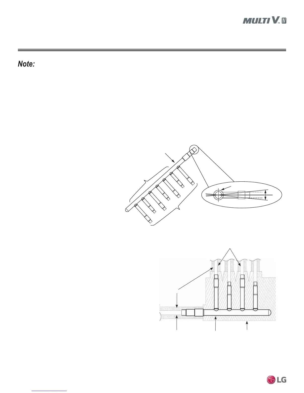
and an indoor unit. Headers must be installed in a horizontal and
level position with the distribution ports of the fitting in the same hori-
zontal plane as the straight-through branch.
When connecting indoor units to a Header, always connect the unit
with the largest nominal capacity to the port closest to the outdoor
unit. Then install the next largest indoor unit to the next port, work-
ing down to the smallest indoor unit. Do not skip ports.
All indoor units connected to a single Header fitting should be
located with an elevation difference between indoor units that does
not exceed 49 feet.
LG supplied insulation jacketLG supplied header
Field supplied copper pipe
Field supplied insulation
Field supplied copper pipe
Figure 25: Header Insulation and Pipe Detail.
Figure 24: Header Kit—Horizontal Rotation Limit (Must be Installed Level with No Rotation).
Smaller IDUs
Connect IDUs
Largest IDU
Header Inlet
Header End View
+0.0
-0.0
REFRIGERANT PIPING DESIGN
No Substitutions
2QO\/*VXSSOLHG<EUDQFKDQG+HDGHU¿WWLQJVFDQEHXVHGWRMRLQRQHSLSHVHJPHQWWRWZRRUPRUHVHJPHQWV7KLUGSDUW\RU¿HOGIDEULFDWHG
7HH¶V<¿WWLQJV+HDGHUVRURWKHUEUDQFK¿WWLQJVDUHQRWTXDOL¿HGIRUXVHZLWK/*0XOWL9,9V\VWHPV7KHRQO\¿HOGSURYLGHG¿WWLQJVDOORZHGLQ
a Multi V IV piping system are 45° and 90° long radius elbows.
Install Correctly
• Y-branches can be installed upstream between the Header and the outdoor unit, but a Y-branch cannot be installed between a header
and an indoor unit.
• To avoid the potential of uneven refrigerant distribution through a header fitting, minimize the difference in equivalent pipe length be-
tween the header fitting and each connected indoor unit.