'XHWRRXUSROLF\RIFRQWLQXRXVSURGXFWLQQRYDWLRQVRPHVSHFL¿FDWLRQVPD\FKDQJHZLWKRXWQRWL¿FDWLRQ
©
/*(OHFWURQLFV86$,QF(QJOHZRRG&OLIIV1-$OOULJKWVUHVHUYHG³/*´LVDUHJLVWHUHGWUDGHPDUNRI/*&RUS
5()5,*(5$17'(6,*1 | 141
Refrigerant Piping Design & Layout Best Practices
LAYOUT BEST PRACTICES
No Pipe Size Substitutions
Use only the pipe size selected by the LATS Multi V pipe system design software. Using a different size is prohibited and may result in a
system malfunction or failure to work at all.
Pipe Supports
A properly installed pipe system should be adequately supported
to avoid pipe sagging. Sagging pipes become oil traps that lead to
equipment malfunction.
Pipe supports should never touch the pipe wall; supports shall be
installed outside (around) the primary pipe insulation jacket. Insulate
the pipe first because pipe supports shall be installed outside
(around) the primary pipe insulation jacket. Clevis hangers should
be used with shields between the hangers and insulation. Field
provided pipe supports should be designed to meet local codes. If
allowed by code, use fiber straps or split-ring hangers suspended
from the ceiling on all-thread rods (fiber straps or split ring hangers
can be used as long as they do not compress the pipe insulation).
Place a second layer of insulation over the pipe insulation jacket to
prevent chafing and compression of the primary insulation within the
confines of the support pipe clamp.
A properly installed pipe system will have sufficient supports to avoid
pipes from sagging during the life of the system. As necessary,
place supports closer for segments where potential sagging could
occur. Maximum spacing of pipe supports shall meet local codes.
If local codes do not specify pipe support spacing, pipe shall be
supported:
• 0D[LPXPRIILYHIHHWƍRQFHQWHUIRUVWUDLJKWVHJPHQWVRISLSHXS
to 3/4" outside diameter size.
• 0D[LPXPRIVL[IHHWƍRQFHQWHUIRUSLSHXSWRRQHLQFKƎ
outside diameter size.
• 0D[LPXPRIHLJKWIHHWƍRQFHQWHUIRUSLSHXSWRWZRLQFKHVƎ
outside diameter size.
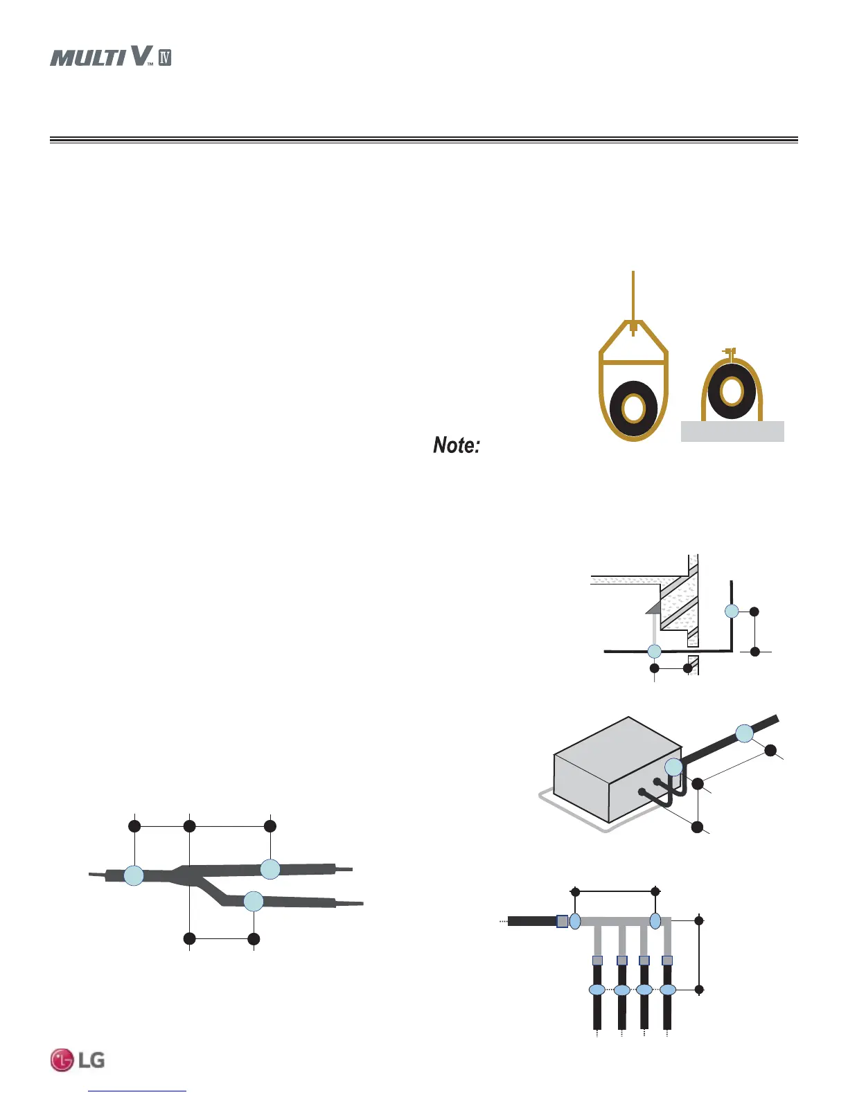
Wherever the pipe changes direction, place a hanger within twelve
(12) inches on one side and within twelve to nineteen (12 to 19)
inches of the bend on the other side. Support piping at indoor units
as shown. Support Y-Branch and Header fittings as shown.
Figure 29: Pipe Hanger Details.
Figure 30: Typical Pipe Support Location—
Change in Pipe Direction.
Figure 31: Pipe Support at
Indoor Unit.
Figure 32: Pipe Support at Y-branch Fitting.
Max. 12"
~ 12" – 19"
A
B
A + B ~ 12" – 19"
Max. 12" Max. 12"
Max. 12"
Max. 12"
Max. 12"
Figure 33: Pipe Support at Header Fitting.
General Information / Guidelines
Use a 4" + long sheet curved sheet metal saddles between hanger
bracket and insulation to promote linear expansion/contraction.